


66 Chapter 3
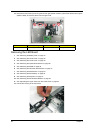
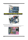
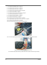
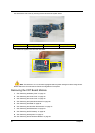
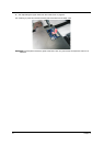
13. Remove the one screw (A) securing the mini board to the system board.
14. Detach the system board from the mini board.
Note: Circuit boards >10 cm² has been highlighted with the yellow rectangle as above image shows.
Please detach the Circuit boards and follow local regulations for disposal.
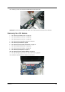
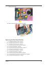
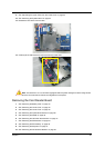
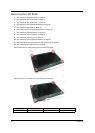
Removing the CRT Board Module
1. See “Removing the Battery Pack” on page 44.
2. See “Removing the Lower Cover” on page 45.
3. See “Removing the Lower Cover” on page 45.
4. See “Removing the Optical Drive Module” on page 46.
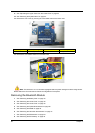
5. See “Removing the DIMM” on page 46.
6. See “Removing the Hard Disk Drive Module” on page 47.
7. See “Removing the SSD Module” on page 48.
8. See “Removing the RTC Battery” on page 49.
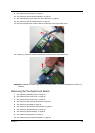
9. See “Removing the Keyboard” on page 51.
10. See “Removing the WLAN Board Module” on page 52.
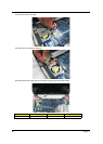
Step Size (Quantity) Color Torque
1 M2 x L4 (1) Black 1.6 kgf-cm