


Chapter 3 49
External Module Disassembly Process
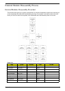
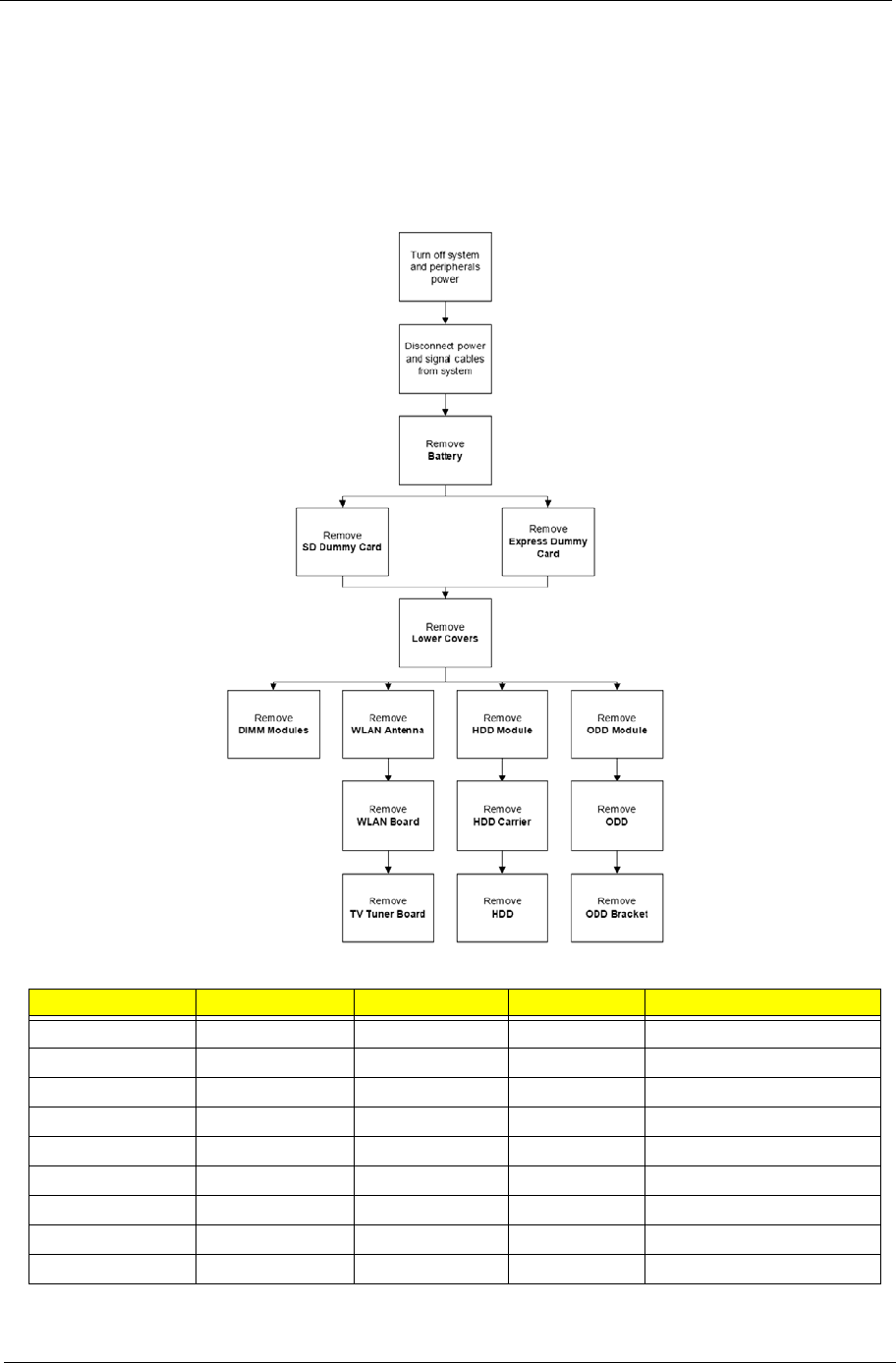
External Modules Disassembly Flowchart
The flowchart below gives you a graphic representation on the entire disassembly sequence and instructs you
on the components that need to be removed during servicing. For example, if you want to remove the main
board, you must first remove the keyboard, then disassemble the inside assembly frame in that order.
Screw List
Step Screw Quantity Color Part No.
Memory Cover M2.5*8 (NL) 4 Black
HDD Cover M2*6 (NL) 2 Black
WLAN Cover M2.5*8 (NL) 4 Black
WLAN Module M2*3 (NL) 2 Black
WLAN Bracket M2*3 (NL) 1 Black
TV Tuner Module M2*3 2 Black
HDD Carrier M3*3 (NL) 4 Silver
ODD Module M2.5*5(NL) 1 Black
ODD Bracket M2*3 (NL) 3 Black