


Chapter 3 47
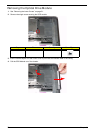
External Module Disassembly Process
IMPORTANT: The outside housing and color may vary from the mass produced model.
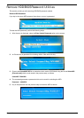
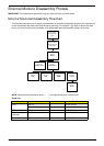
External Modules Disassembly Flowchart
The flowchart below gives you a graphic representation on the entire disassembly sequence and instructs you
on the components that need to be removed during servicing. For example, if you want to remove the main
board, you must first remove the keyboard, then disassemble the inside assembly frame in that order.
NOTE: Items enclosed with broken lines (— - - —) are optional and may not be present.
Screw List
Step Screw Quantity Part No.
ODD M2.5*5 1 86.PH702.005
M2*3 2 86.PH702.002
HDD M3*3 4 86.PH702.004
TV Tuner
(optional)
M2*3 2 86.PH702.002
WLAN Module M2*3 2 86.PH702.002
Disconnect power
and signal cables
from system
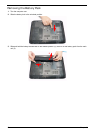
Remove
Battery
Turn off system
and peripherals
power
Remove
DIMMs
Remove
WLAN
Remove
HDD
Remove
ODD
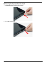
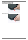
Remove
Lower Covers
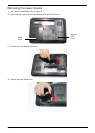
Remove
Dummy Cards
Remove
TV Tuner