


PANEL1000-370 All-in-One PANEL PC User’s Manual
System Installation
10
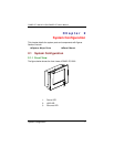
3.1 CPU
The standard PANEL PC 1000 system already builds in Pentium
III-level CPU. When upgrading to a new CPU of the same level, follow
the instructions below;
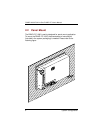
1.
To remove the existing CPU requires the use of a chip
puller.
2.
Locate pin 1 at the corner of the CPU socket and align
the CPU’s pin 1 with the pin 1 on the socket.
3.
Place the CPU in the socket. If the insertion of the CPU to
the socket is not easy, then check whether the notch on
the corner of the CPU and the notch on the socket are
properly aligned.
4.
When a new CPU is installed, other settings on the system
control board including CPU type, CPU bus clock and
CPU voltage may need to be adjusted. Make sure all the
settings are correct for the installed CPU. (See the CPU
jumper settings in the CPU card User’s Manual that came
with the PANEL PC packaging).
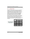
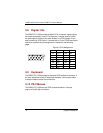
3.2 DRAM
The system control board provides
1 x 168-pin DIMM
sockets
supporting system memory up to 256MB.
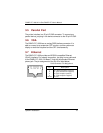
To install the memory module;
1.
Disconnect all power sources.
2.
The memory module can only fit into the socket one way.
Holding the memory module with the notch on the upper
right corner, then insert the memory module at a 45°
Angle and push the module upright until it clicks into
place.
The system auto detects the new memory size and it is not necessary
to change the system configuration after installation.