


78
Border Artifacts
Border artifacts are a general category of image artifacts that may show up on screen in
the area outside of the active array. Border artifacts include: Exposed Bond Wires,
Exposed Metal 2, and Reflective Edge.
Bond Wires
Bond Wires are the electrical connections between the die and the DMD ceramic
package. If visible, they will appear as short light parallel lines outside of the
Pond of Mirrors (POM).
Exposed Metal 2
Exposed Metal 2 is due to a shift in positioning of either the die or the window
aperture, which may allow light to be reflected off of the layer of metal 2 that is below the
super structure (mirrors). This defect is located outside of the POM.
Reflective Edge
Reflective Edge is light that may reflect from the edge of the DMD window aperture onto
the projection screen. It will appear as a thin diffuse line outside of the POM.
Blue 60 Screen
The Blue 60 screen is used to test for major dark blemishes. All areas of the screen are
colored a Microsoft Paintbrush blue 60 (green and red set at 0, blue set at 60). NOTE: If
linear degamma is not used then the Microsoft Paintbrush values must be adjusted to
match the degamma table being used in order to generate an equivalent blue level on the
test screen image.
Gray 10 Screen
The Gray 10 screen is used to test for major light blemishes. All areas of the screen are
colored a Microsoft Paintbrush gray 10 (green, red, and blue set at 10).
NOTE: If linear degamma is not used then the Microsoft Paintbrush values must be
adjusted to match the degamma table being used in order to generate an equivalent gray
level on the test screen image.
Gray 30 Screen
The Gray 30 screen is used to test for the reset boundary artifact. All areas of the screen
are colored a Microsoft Paintbrush gray 30 (green, red, and blue set at 30).
NOTE: If linear degamma is not used then the Microsoft Paintbrush values must be
adjusted to match the degamma table being used in order to generate an equivalent gray
level on the test screen image.
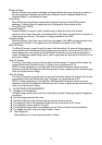
3. ACCEPTANCE REQUIREMENTS
3.1 Conditions of Acceptance
All DMD image quality returns will be evaluated using the following projected image test
conditions:
Test Set degamma shall be linear.
Test Set brightness and contrast settings shall be set to nominal.
The diagonal size of the projected image shall be a minimum of 60 inches.
The projection screen shall be 1X gain.
The projected image shall be inspected from an 8 feet minimum viewing distance.
The image shall be in focus during all Table 1 tests.
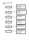
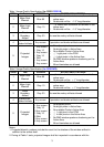
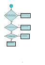
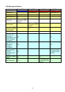
3.2 Test Sequence
Tests shall be run in the sequence listed in Table 1.