


49
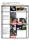
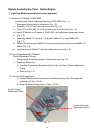
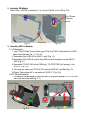
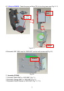
2. Assembly FM Module:
Place FM on “HLD FM” surface(Fig. 2-1) and use “Clip FM” to fix FM(Fig. 2-2).
Fig. 2-1 Fig. 2-2
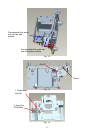
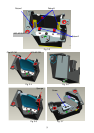
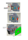
3. Assembly HSG ILL Module:
3.1 CM Assembly
I. Insert “Clip CM Side” first, and then place “Clip Front CM” to fixed-shaft of ILL SUB
before locking screw (Fig. 3-1, Fig. 3-2).
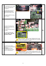
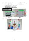
II. Assemble Mylar SUB HSG to HSG ILL well (Fig. 3-3).
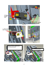
III. Assemble CM to HSG ILL and to make CM contact three datum on the HSG ILL
Well (Fig. 3-3).
IV. Assemble” MYLAR CM ” to the CMD firstly, “CLIP TOP CM”(with forceps) to the
“HSG ILL” (Fig. 3-4,).
V. To check and make sure “CLIP of CM” hooks the HSG ILL very Well (Fig. 3-5).
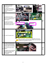
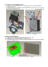
VI. Paste “Sponge tube AL” on cannelure of” HSG ILL” (Fig. 3-6).
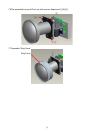
3.2 FM Module Assembly
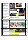
i. FM Module must be placed to fixed shaft and on the datum surface of “ILL SUB” and
then lock with screw well (Fig. 3-7).
Fig. 3-1 Fig. 3-2
Touch the
side surface
Clip FM hook
the punch
points
Clip CM Side
Screw
Fixed shafts
of ILL SUB