


Chapter 3 41
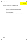
Disassembly Procedure Flowchart
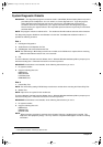
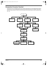
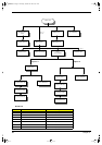
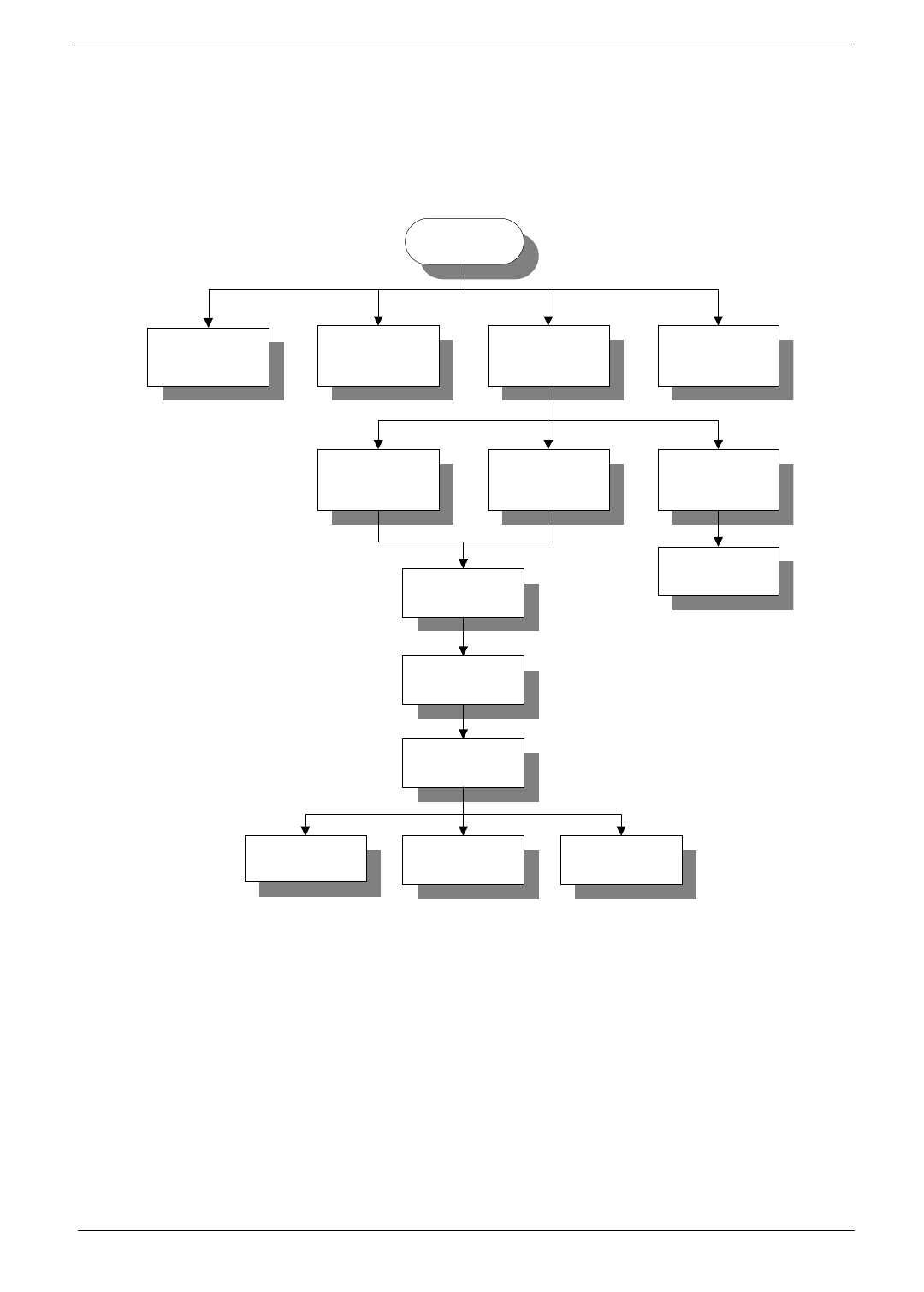
The flowchart on the succeeding page gives you a graphic representation on the entire disassembly sequence
and instructs you on the components that need to be removed during servicing. For example, if you want to
remove the system board, you must first remove the keyboard, then disassemble the inside assembly frame in
that order.
START
HDD Module
Extended DIMM
Cover
Middle Cover Batter
y
LCD FPC
Cable
Main Unit
(
see next pa
g
e
)
Ke
y
boardInverter Cable
LCD Module
LCD Bezel
LCD and
Inverter Board
LCD FPC
Cable
Inverter/ LED
Board
Inverter/LED
Cable
A x 1 B x 2
A x 2
A x 2
C x 2
D x 4
E x 6
340SG.book Page 41 Thursday, October 28, 1999 10:51 AM