


Installing a D3LX CO Module in an LEC LTPS-UM-8013-03
10 August 30, 2002 D3LX CO and RMT Modules
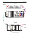
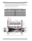
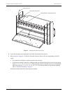
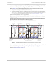
Figure 5. Routing the Fiber Patch Cord
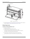
4 Locate the mounting slots designated for the D3LX CO modules in the chassis.
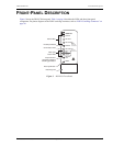
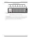
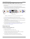
5 Refer to Figure 6 on page 11 for D3LX CO module locations chassis and slot corresponding to the DS3
signal.
– If no protection switching is required, proceed to the next step.
– If protection switching is required, a working module may be installed in the first slot of any quad group,
such as 1-1, 2-1, 3-1, 4-1, 5-1, 6-1, or 7-1. The protection module is installed in the slot to its immediate
right in the order of 1-3, 2-3, 3-3, 4-3, 5-3, 6-3, or 7-3. For more information on protection switching,
refer to “Protection Switching” on page 4.
Install the working module first, then the protect module.
FiberGuide vertical duct
Heat baffle/fiber management panel
Fiber patch cord