


LTPS-UM-8013-03 Setting Up System Options
D3LX CO and RMT Modules August 30, 2002 19
OTHER PROVISIONING CONSIDERATIONS
Alarm Setting During Provisioning
The D3LX generates alarms on conditions occurring in the D3LX CO modules DS3 facility. The severity of the
alarm conditions as Critical, Major, Minor, or Event is selected while provisioning. The alarms are handed off to
an Alarm Processing Unit (APU) which acts as an interface between the D3LX modules and the customer alarm
monitoring equipment. For more information on alarms, see “Configuring D3LX Alarms” on page 25.
D3 Remote Craft Access Module (D3RCAM) Option
The D3RCAM is a plug-in module for the D3LX system which provides a craft interface at the remote site.
Additionally, the D3RCAM works in conjunction with the APU and the D3LX modules to display alarm
information for the remote chassis or terminal.
SETTING UP SYSTEM OPTIONS
To configure D3LX system options, you must connect a maintenance terminal to an available craft port. You may
select either the SCU or Ports 2 or 3 (local) or the D3RCAM (remote) craft port.
• If you are using the SCU, refer to “Connecting a Maintenance Terminal to the SCU Craft Port” on page 19.
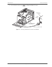
• If you are using the D3RCAM, refer to “Connecting a Maintenance Terminal to the D3RCAM Craft Port” on
page 20.
CONNECTING A MAINTENANCE TERMINAL TO THE SCU CRAFT PORT
Connect the VT100 compatible terminal or host computer to the interface port as follows:
1 For initial setup, connect the local maintenance terminal to the SCU craft port (on front panel). After
configuration, the SCU may be connected to ports 2 or 3 on the backplane of the LEC. For more information
on Ports 2 and 3 located on the LEC, refer to Soneplex Loop Extender System Operation and Maintenance
Manual, ADCP-61-494. See Table 3 for chassis port descriptions.
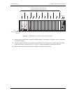
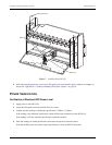
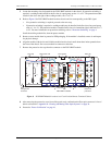
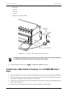
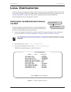
2 Connect one end of the interface cable to the maintenance terminal and the other end to the craft port located
on the front of the SCU as shown in Figure 11.
3 Start a terminal emulation program such as Procomm that emulates a VT100 terminal.
4 Configure the maintenance terminal to the following communication settings:
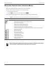
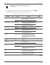
Table 3. Chassis Port Description
SCU Front-Panel Craft Port Ports 2 and 3
Function—DCE connection on the installed SCU module (see Figure 11 on
page 20)
DTE connections on the chassis backplane. Ports
provide an RS (EIA-232) interface.
Cable Type—Straight-through cable (26 AWG or larger, stranded pairs,
overall shielding, common for all leads).
A null-modem cable or adapter.
Connector—Type DB-9 receptacle. Type DB-25 receptacle.