


Installing a D3LX RMT Module in a Remote Cabinet LTPS-UM-8013-03
16 August 30, 2002 D3LX CO and RMT Modules
TWO-POSITION QLX REMOTE BNC CHASSIS INSTALLATION
To install first the working module, and then the protect module (if installing D3LX RMT modules in protection
switching applications):
1 Open the front panel of the remote terminal into which the D3LX RMT will be installed.
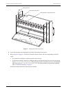
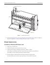
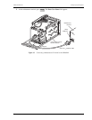
2 Route the fiber patch cord through the left side of the fiber management enclosure located on the remote
terminal as shown in Figure 10. The protective cover must remain on the fiber connector to prevent dust and
damage to the connection. The fiber should be tagged to identify the circuit.
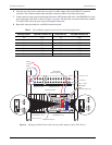
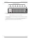
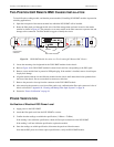
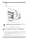
Figure 10. D3LX RMT Module Locations in a Two-Position QLX Remote BNC Chassis
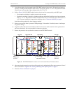
3 Locate the mounting slots designated for the D3LX RMT modules in the chassis.
4 Refer to Figure 10 for D3LX RMT module locations chassis and slot corresponding to the DS3 signal.
5 Remove a new module from its protective ESD packaging. If the module is installed, remove it and inspect
for physical damage.
6 Align the module with the slot and slide the module into the chassis until about three inches protrude from
the front of the chassis. Do not seat module in connector at this time.
7 Remove the protective dust cap from the connector on the D3LX RMT module.
8 After removing the protective cover from a fiber patch cord, confirm that the fiber-optic connector is free of
debris as directed in “Appendix B - Cleaning and Mating Fiber-Optic Systems” on page 39.
9 Proceed to “Power Verification” on page 16.
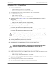
POWER VERIFICATION
Verification of Electrical DS3 Power Level
1 Apply power to the D3LX RMT.
2 Attach the fiber patch cord from the D3LX RMT to a meter.
3 Confirm that the readings are within the specification (-5 dBm to -23 dBm).
If the reading is not within the specification, check all fiber-optic connections to the D3LX RMT.
If the reading is still not within the specification, replace the module.
4 Once the readings are within specification, disconnect the patch cord from the meter.
Now that the DS3 power level meets optical specifications, verify the D3LX RMT module.
Fiber
management
enclosure
CR
MJ
MN
ACO
PWR
HSKP
RMT
ALM
DISP RMT
A
P
U
D3LX RMT
OPT
APS
STATUS
FAR END
DS3 STATUS
DS3 ONLINE
LMPTST/
APS
RESET
ENABLE
FAIL
BER
LOCKOUT
FORCE
R=FAULT
G=O.K.
FLASH=LBK
OFF=UNEQPP
G=ONLINE
OFF=OFFLINE
STATUSSTATUS
D3RCAM
RESET
C
R
A
F
T
D3LX RMT
OPT
APS
STATUS
FAR END
DS3 STATUS
DS3 ONLINE
LMPTST/
APS
RESET
ENABLE
FAIL
BER
LOCKOUT
FORCE
R=FAULT
G=O.K.
FLASH=LBK
OFF=UNEQPP
G=ONLINE
OFF=OFFLINE
D3LX RMT modules
D3RCAM
APU