


Installing a D3LX RMT Module in a Remote Cabinet LTPS-UM-8013-03
14 August 30, 2002 D3LX CO and RMT Modules
INSTALLING A D3LX RMT MODULE IN A
REMOTE CABINET
Use the following procedure to install D3LX RMT modules in a Four-Position Remote Terminal Cabinet or
Two-Position QLX Remote BNC Chassis. After installing the D3LX RMT modules in either chassis, proceed to
“Power Verification” on page 16.
FOUR-POSITION REMOTE TERMINAL CABINET INSTALLATION
To install first the working module, and then the protect module (if installing D3LX RMT modules in protection
switching applications):
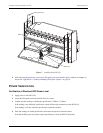
1 Open the front panel of the remote terminal into which the D3LX RMT will be installed.
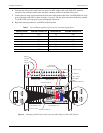
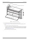
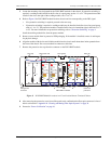
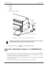
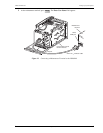
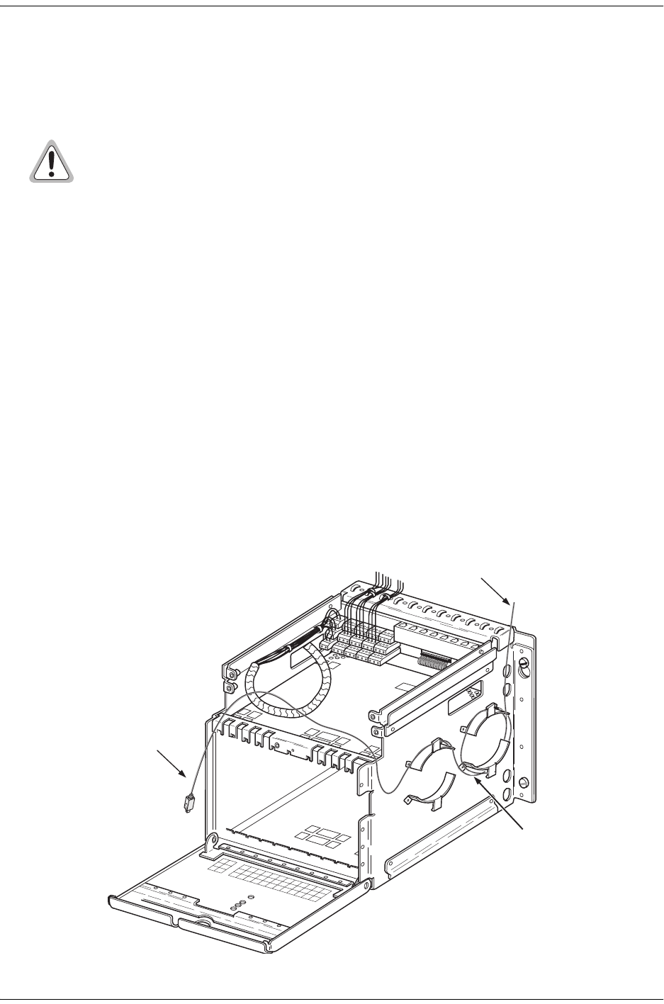
2 Route the fiber patch cord through the top of the chassis and around the radius limiters as shown in Figure 8.
The protective cover must remain on the fiber connector to prevent dust and damage to the connection. The
fiber should be tagged to identify the circuit.
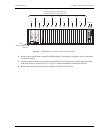
Figure 8. Routing the Fiber Through a Four-Position Remote Terminal Cabinet
Avoid exposure to invisible laser radiation.
• Do not look into the ends of any optical fiber or directly into the module fiber connectors as
exposure to invisible laser radiation may result.
• Use a meter to verify active fibers.
• Do not insert module edge connectors into the chassis connectors before connecting the
optical fiber to the module. Verify that LED indicators are not lit, and the module is not
engaged with the chassis connectors before proceeding.
Fiber-optic loop
Fiber-optic patch cord
Radius limiters