


Appendix A - Specifications LTPH-UM-1049-02, Issue 2
66 January 9, 2002 H2TU-C-319 List 4E
POWER CONSUMPTION
The three most important power parameters of an H2TU-C are its maximum power consumption, maximum
power dissipation, and maximum current drain.
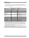
Table 26 describes line-powered circuits on 9 kft, 26 AWG loops without a regenerator.
MAXIMUM POWER DISSIPATION
The Maximum Power Dissipation measures the power that is converted into heat that builds up within the unit. It
contributes to the total heat generated in the space around the unit. It is used to determine the maximum number
of fully loaded shelves per bay that does not exceed the maximum allowable power dissipation density in watts
per square foot to comply with GR-63.
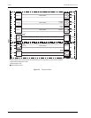
In COs, the maximum power dissipation for open-faced, natural convection-cooled mountings is limited to
134.7 watts per square foot per GR-63-CORE. The footprint of a standard 28-slot, 23-inch HMS-317 shelf is 7.024
square feet. Therefore, the maximum bay dissipation is limited to 946 watts. Use this limit and the parameters in
Table 26 to determine the maximum number of H2TU-C circuits that can occupy one CO bay.
The thermal loading limitations imposed when using the H2TU-C in a Controlled Environmental Vault (CEV) or
other enclosures are determined by applying its power parameters to the manufacturer's requirements for each
specific housing.
The -48 Vdc Power Consumption is the maximum total power that the H2TU-C consumes or draws from the shelf
power source. This parameter is needed when the H2TU-C is in a location remote to the CO it is serving. It
determines the battery capacity required to maintain an 8-hour, standby battery reserve for emergency situations.
Battery capacity, therefore, limits the maximum number of line units which can be installed in a remote enclosure.
Use the data in Table 26 above to perform this analysis.
MAXIMUM CURRENT DRAIN
The Maximum Current Drain is the maximum current drawn from the shelf power supply when it is at its
minimum voltage (-42.5
Vdc). This determines the shelf fusing requirements. Use the -42.5 Vdc current data in
Table 26 above to determine the shelf fusing requirements for your particular H2TU-C applications.
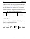
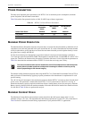
Table 26. H2TU-C-319 List 4E Power Parameters
-48 Vdc Power
Consumption
(Watts)
Heat Dissipation
(Watts)
-42.5 Vdc Current
(mA)
Remote Power Source Maximum Maximum Maximum
Line-powered 12.25 7.25 292.0
Local-powered with Sealing Current 8.7 6.75 207.0
This is a worst case situation since it assumes the entire CO is subjected to the maximum power
density. More favorable conditions would permit increasing the number of shelves per bay
without jeopardizing the CO thermal integrity.