


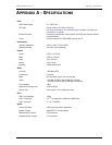
Appendix A - Specifications LTPH-UM-1049-02, Issue 2
68 January 9, 2002 H2TU-C-319 List 4E
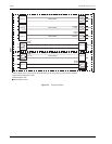
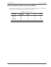
H2TU-C-319 LIST 4E CARD-EDGE CONNECTOR
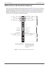
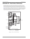
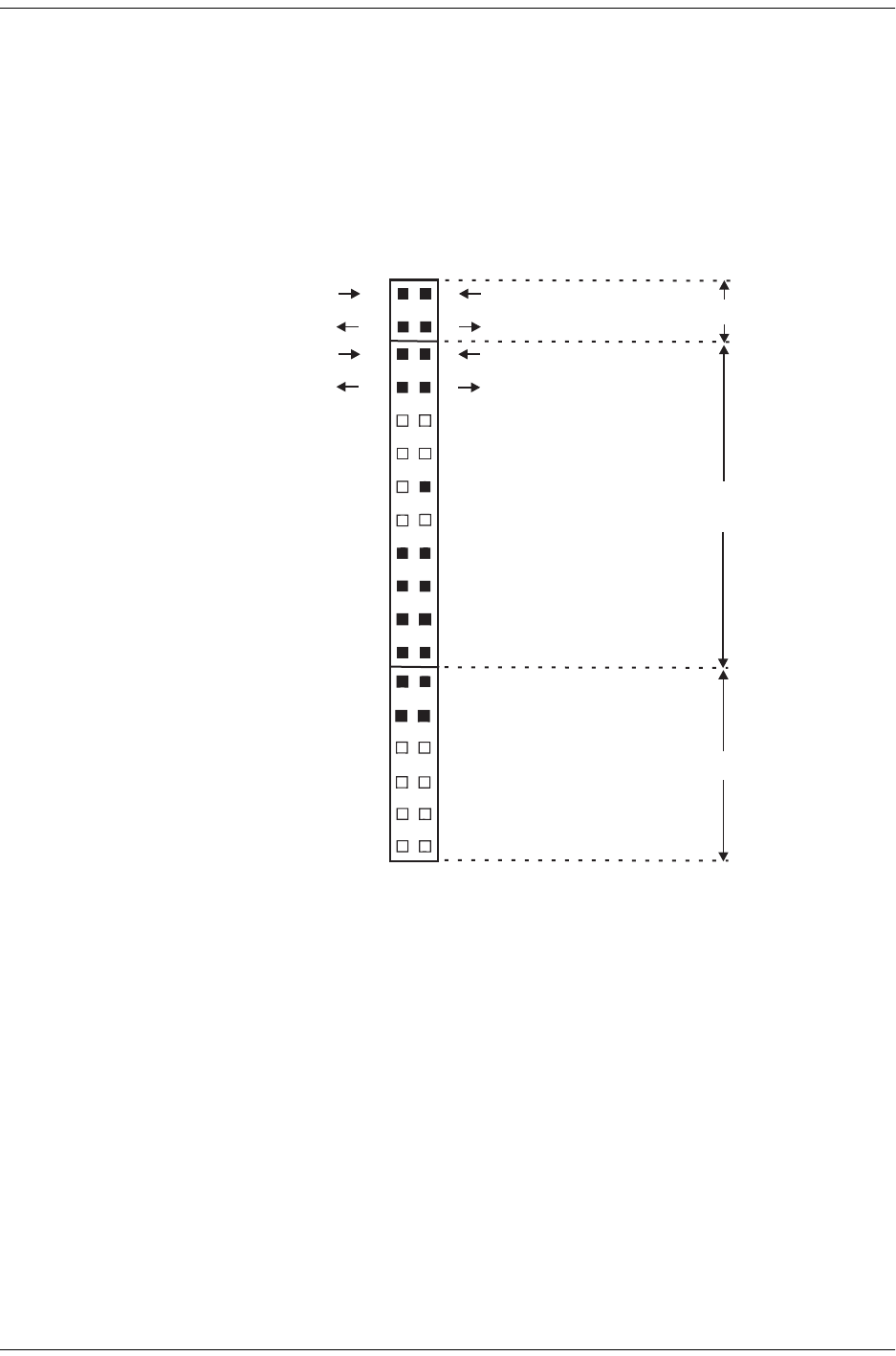
Figure 33 shows the pin assignments of the card-edge connector on the H2TU-C-319 List 4E card. The function
of its segments (S1, S2, and S3) are described beginning with “Test Access” on page 28. Note that only the set of
Standard 3192 alphanumeric connector pins to Segment 3 (A through L and 1 through 10) are labeled on the
backplane of the HMS-358 shelf. The outer set of pin numbers are for reference only and do not appear on the
backplane. The AUX DSX-1 Segment 1 port can be accessed either by its wire wrapped pins or from mass
connector P11 (TX) and P10 (RX) on the HMS-358 backplane.
Figure 33. H2TU-C-319 List 4E Card-Edge Connector
3
4
5
6
C
D
E
F
H7
8
J
9
K
10
L
GND
HDSL2SpanTip
HDSL2SpanRing
System alarm
Management bus
Frame ground
-48V BAT
Fusealarm*
Factoryuseonly
1
A
(IN)DSX-1Tip
DSX-1Ring(IN)
2
B
(OUT)DSX-1 Tip1
DSX-1Ring1(OUT)
* Fuse alarm is normally floating
and at -48Vdc when activated.
1
19
(IN)DSX-1Tip
DSX-1Ring(IN)
2
20
(OUT)DSX-1 Tip1
DSX-1Ring1(OUT)
13
14
31
32
33 15
16
34
17
35
18
36
{
MUXPort
{
AUXPort
{
MUXPort
{
AUXPort
(OUT)MATIF Tip
(IN) TipMATIE
{
Metallic
MATIF (OUT)Ring
MATIE Ring(IN)
{
Access
(TB6)
Metallic Access
(TB6)
** Segment 3 (A - L and 1 - 10) are
connector pins as reflected on the
labels on the backplane of the
HMS-358 shelf.
from standard 3192 alphanumeric
Segment2
Segment1
Segment3*