


LTPH-UM-1049-02, Issue 2 Appendix A - Specifications
H2TU-C-319 List 4E January 9, 2002 69
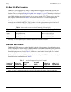
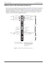
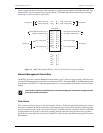
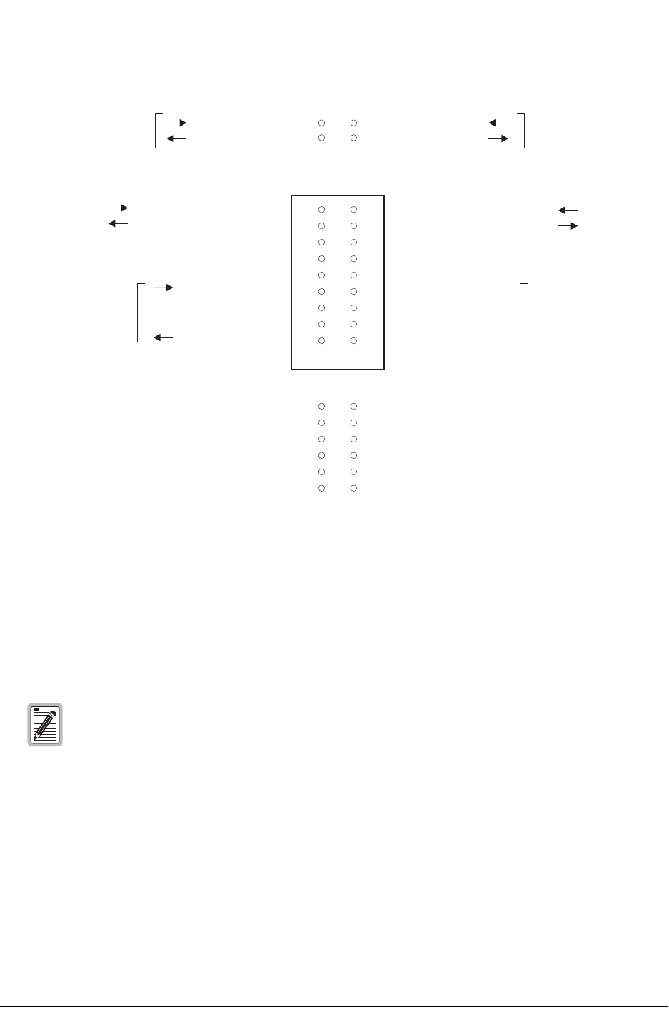
Figure 34 shows the generic labeling of the connector as it appears on the backplane with HMS-358 shelf. Note
that the H2TU-C has no connections to Loop B of Group 1. The HMS-358 technical practice refers to Group 1
and Group 2 as Port 1 and Port 2, respectively.
Figure 34. HMS-358 Backplane H2TU-C-319 List 4E Card Edge Connector Labeling
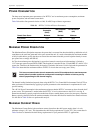
Network Management Control Bus
The H2TU-C provides a Network Management Control Bus on pin 7 of the card-edge connector. This allows the
various ADC Management System protocols to manage the H2TU-C through the HMU-319 HiGain Management
Unit. Whenever the H2TU-C is under management, the MNGD message displays periodically on the front-panel
display.
Fuse Alarm
Pin 10 on the card-edge connector is a Fuse Alarm that is driven to -48 Vdc through a diode whenever its onboard
fuse opens. It emulates the function of the Fuse Alarm output from pin 10 on normal, high density (HD) repeaters.
pin 10 is connected to pin 5 of the 1184 Alarm Card (slot 1 in the HD shelf) and causes the 1184 Fuse ALM LED
to light when the pin 10 signal is activated. Its normally floating output must never be driven above ground or
below -80 Vdc. It can sink a current of 10 mA. The H2TU-C does not support the BPV function (pin E) of normal
HD repeaters.
Some H2TU-C features are affected when it is under management. Consult the management unit
practice for further information.
3192 MECH
Group Port 2 Group Port 2
Group Port 1 Group Port 1
21
19
20
21
22
22
23
23
24
24
25
25
26
26
27
28
29
3
1 AUX (Loop A) RingAUX (Loop A)Tip
AUX (Loop B) RingAUX (Loop B)Tip 2
3
1ADSX (XMT from MUX) Tip DSX (XMT from MUX) Ring
DSX (RCV to MUX) Tip DSX (RCV to MUX) Ring
Line (Loop A) Tip Line (Loop A) Ring
Line (Loop B) Tip Line (Loop B) Ring
4
4
2B
5
5
3C
6
6
4D
7
7
5E
8
8
6F
97
10 8
H
11 9
J
10
K
L