


ADCP-61-743 • Issue 3 • September 2004
Page 17
© 2004, ADC Telecommunications, Inc.
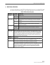
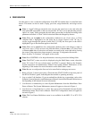
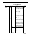
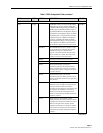
Table 3. RTAU Configuration Fields, continued
FIELD TYPE OPTIONS DESCRIPTION DEFAULT
EQUIPMENT SETUP FIELDS, continued
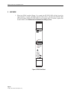
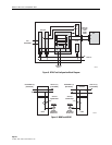
Mode Toggle OVERVIEW: Valid access modes and the resulting
configurations are shown in Figure 8 (RTAU Test
Configuration Block Diagram), Figure 9 (MONF and
MONE), Figure 10 (SPLTB and SLPTA), Figure 11
(Typical Round-Robin Test Configuration), Figure 12
(Typical End Test Configuration), Figure 13 (SPLTF
and SLPTE), Figure 14 (Typical Point-to-Point Test
Configuration), Figure 15 (SPLTFL and SPLTEL),
and Figure 16 (LOOPF and LOOPE). In addition,
when the Mode field change is saved by pressing the
Enter or Return key, the MPU or SCU will instruct
the DS3 MUX to drop and insert the selected circuit.
DISABLE
DISABLE When DISABLE is selected, no monitor or split
access can take place. Setting the Mode field to
DISABLE also stops any measurement in
progress, as if the Measurement field (described
below) had been set to STOP. The tested circuit
will also be restored to normal operation.
MONE Non-intrusive monitor access to the A pair.
MONF Non-intrusive monitor access to the B pair.
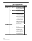
SPLTA SPLTA mode indicates a split in the A
transmission path with a Test Signal Generator
(TSG) connected in the F direction, and a Signal
Presence Detector (SPD) connected to the signal
from the E direction.
SPLTB SPLTB mode indicates a split in the B
transmission path with a TSG connected in the E
direction and an SPD connected to the signal from
the F direction.
SPLTE SPLTE mode indicates a split in both the A and B
transmission paths. An SPD is connected to the line
incoming from the E direction and a TSG is
connected to the line outgoing to the E direction. The
line outgoing in the F direction is connected to a
QRSS source and the line incoming from the E
direction is terminated by the nominal characteristic
impedance of the line.
SPLTF SPLTF indicates a split in both the A and B
transmission paths with a TSG connected to the line
outgoing to the F direction and an SPD connected to
the line incoming from the F direction. The line
outgoing in the E direction is connected to a QRSS
source and the line incoming from the E direction is
terminated by the nominal characteristic impedance
of the line.
(continued)