


ADCP-61-743 • Issue 3 • September 2004
Page 8
2004, ADC Telecommunications, Inc.
14185-A
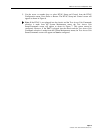
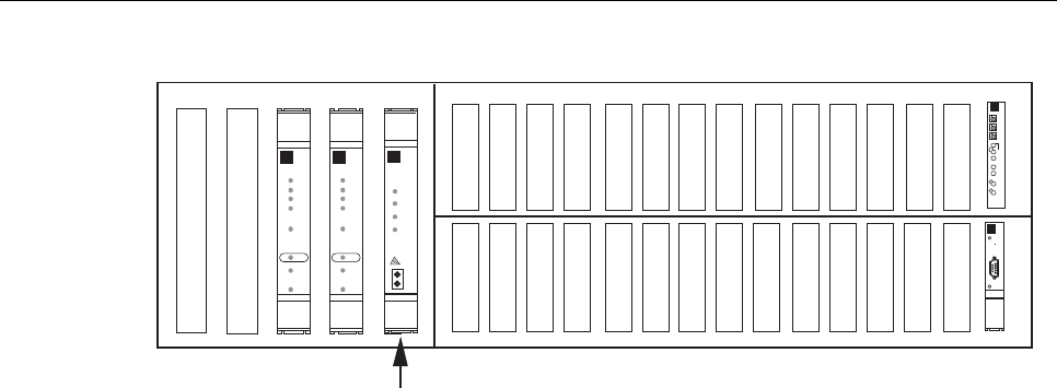
RTAU MODULE
HSW
HSP
TAU
APU
SCU
MXPMXW
DS3 FAIL
RESET
LMPTST/
APS
LPBK
ENABLE
ONLINE
STATUS
APS
LOCKOUT
FORCE
CR
MJ
MN
APU
ACO
PWR
HSKP
RMT
ALM
LMPTST
DISP RMT
1-31-1 2-1 2-3 3-1 3-3 4-1 4-3 5-1 5-3 6-1 6-3 7-1 7-3
1-41-2 2-2 2-4 3-2 3-4 4-2 4-4 5-2 5-4 6-2 6-4 7-2 7-4
RTAU
INTRUSIVE
TEST
B8ZS
AMI
LINE CODE
STATUS
D
S
1
RX
TX
DS3 FAIL
RESET
LMPTST/
APS
LPBK
ENABLE
ONLINE
STATUS
APS
LOCKOUT
FORCE
STATUS
RESET
C
R
A
F
T
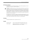
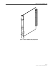
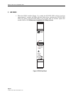
Figure 2. RTAU Mounting Position in the Soneplex Broadband
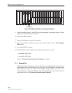
5. Align the module edges of the RTAU with the mounting slot module guides. Use the
injectors to seat the module in the chassis.
6. Remove the RTAU module.
7. Inspect the backplane connector for bent pins.
8. If pins are not bent, continue to the next step. If pins are bent, refer to 2.1.1 Damaged
Pins section.
9. Re-install the RTAU module.
10. With the RTAU module installed, power up the shelf one fuse at a time.
a. Install the -48V A fuse.
b. Install the -48V B fuse.
Refer to 8. Customer Information and Assistance, if needed.
2.1.1 Damaged Pins
The pins used in the back plane connector should not be straightened after they have been
deflected more than 10 degrees from vertical as they will “work harden” and break at the
bend. Bent pins must be removed and replaced using special tools and is not
recommended as a field repair. Remove shelf with damaged pins and contact ADC for
replacement. Refer to 8. Customer Information and Assistance.