


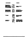

AdderView DVI Installation and Use Page 26
3.6 RS232 control
AdderView DVI can be controlled by a remote RS232 device. To select a channel
the data rate of the sending device must be set to 1200 baud, 8 bits, no parity and 1
stop bit. No handshaking is used by the AdderView DVI. Simply send the character
for the channel which needs to be selected, for example ASCII ‘1’ (hex code 31) will
select channel 1, ASCII ‘2’ (hex code 32) will select channel 2 and so on. The
AdderView will echo the ASCII character back to the sending device when the
channel has been changed. The serial interface pins are found on the options
connector on the rear of the AdderView. Pin assignments for this connector are
given in appendix A.
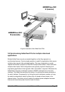
3.7 Cascading AdderView DVIs
AdderView DVI switches can be connected together to expand the number of
connected computers. When cascading AdderView DVIs a power adapter
(AVGPSU) must be connected to each AdderView DVI. AdderView DVIs can be
connected in a cascaded tree structure. This can be particularly useful where
clusters of computers are located some distance from each other because each unit
acts as data booster and can each be up to 5 metres away from the next AdderView
DVI. The channel can be selected on remote AdderView DVI units using an
extension of the HOTKEY control .
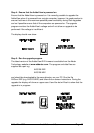
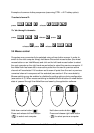
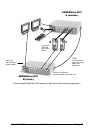
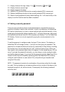
For example, consider a situation where two AdderView DVI units are connected
together as shown below. To connect to the computer attached to port 3 on
AdderView DVI B the user would hold down the hotkey keys then press ‘2’ followed
by ‘3’, whilst keeping the hotkey keys pressed. This will have the effect of connecting
to port ‘3’ of the AdderView DVI which is connected into port ‘2’ of the first
AdderView DVI unit A.
For example to connect to port 3 on the AdderView DVI cascaded off port 2 of your
first AdderView DVI use:
press
baba
22release 22
press 33release 33
baba