


welcome contents
installation
& operation
special
configuration
furter
information
13
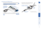
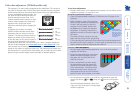
Video skew adjustment (X200AS models only)
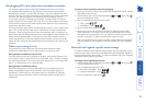
The category 5, 5e and 6 cabling supported by the AdderView CATx consists of
four pairs of wires per cable. Three of these pairs are used to convey red, green
and blue video signals to the remote video monitor. Due to the slight difference
in twist rate between these three pairs, the
red, green and blue video signals may not
arrive at precisely the same time. This is
visible as separate colour shadows on high
contrast screen images and is particularly
apparent when using higher screen
resolutions and some types of category 5e
cables.
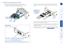
To alleviate this situation, the Adder
X200AS modules provide internal skew
adjustment that can help to rectify the
situation. The skew adjustment works by
delaying or advancing the timing of any
of the red, green or blue colour signals so
that they are all delivered to the monitor
at precisely the same time. For best results, the “skew” program supplied on
the disk or downloadable from www.adder.com or www.adder.info is the
most accurate way of setting skew as the red, green and blue lines are rendered
exactly on the screen as single pixel wide lines. The skew.bmp test pattern can
also be used but it is less accurate. Alternatively, you can create your own skew
pattern using a standard image creation package, as detailed opposite.
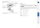
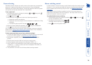
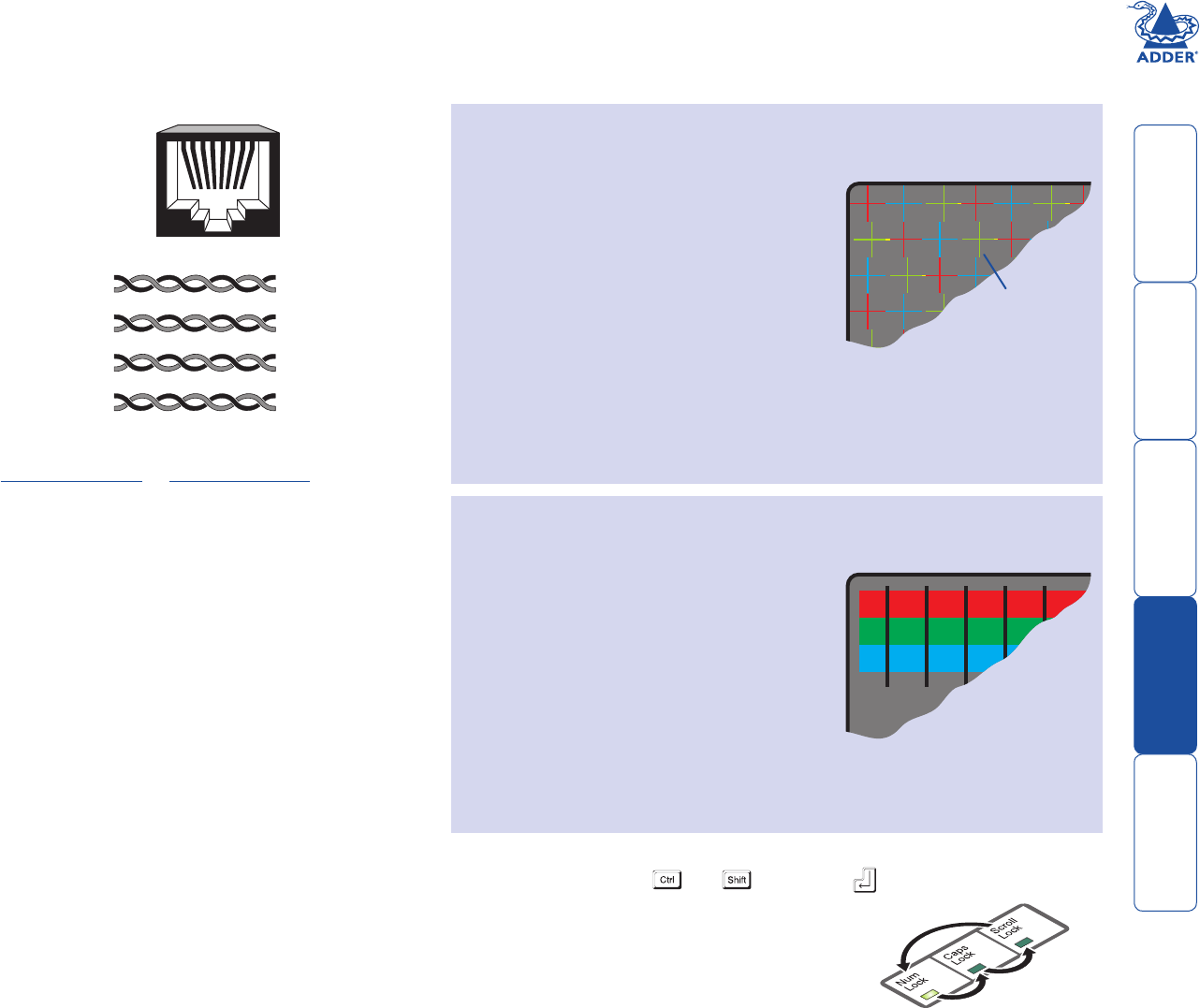
Convergence test
pattern showing the
RGB crosses. In this
case, the green signal
can be seen out of
line with the other
two colours.
1 2 34 56 78
8
6
5
2
8
6
5
2
Datasignal
Red
video signal
Green
video signal
Blue
video signal
7
3
4
1
7
3
4
1
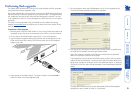
To use skew adjustment
1 Display a skew pattern on the appropriate computer. You can either use the
supplied skew pattern or create your own:
Using the supplied skew pattern
i Insert the supplied Adder Installation CD-ROM into the CD player of the
computer.
ii Within Windows, use the My Computer
option (usually available as a desktop icon
or within the Start menu) to view the
contents of the CD-ROM. Double-click
the Skew entry to display the standard
test pattern. If necessary, maximise the
application window so that the image fills
the screen.
The screen will show a series of fine red,
green and blue crosses which should all be
in line, vertically and horizontally. Skew affects the horizontal placement of
the colours and using this pattern it is much easier to discover which, if any,
colours are being adversely affected by the cable link.
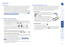
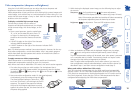
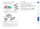
Creating a skew test pattern
skew test pattern
i Run any image creation/editing application, such as the Paint program
supplied with Windows.
ii Using the image application create three
stacked horizontal rectangles (one red,
one green and one blue) that fill the
width of the screen.
iii Draw a vertical black line down across
the coloured bars and then repeat this
vertical line at intervals along the width
of the coloured bars. These lines create
breaks across the colours and give you
more opportunities to view the horizontal
position of each colour relative to the others.
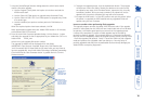
2 On the keyboard connected to the X200AS, simultaneously, press the
hotkeys (by default, and ) along with to enter configuration
mode.
The three keyboard indicators (‘Num Lock’,
‘Caps Lock’ and ‘Scroll Lock’) will now begin
to flash in sequence.