


welcome contents
installation
&operation
special
configuration
furter
information
5
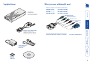
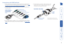
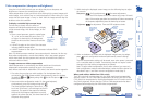
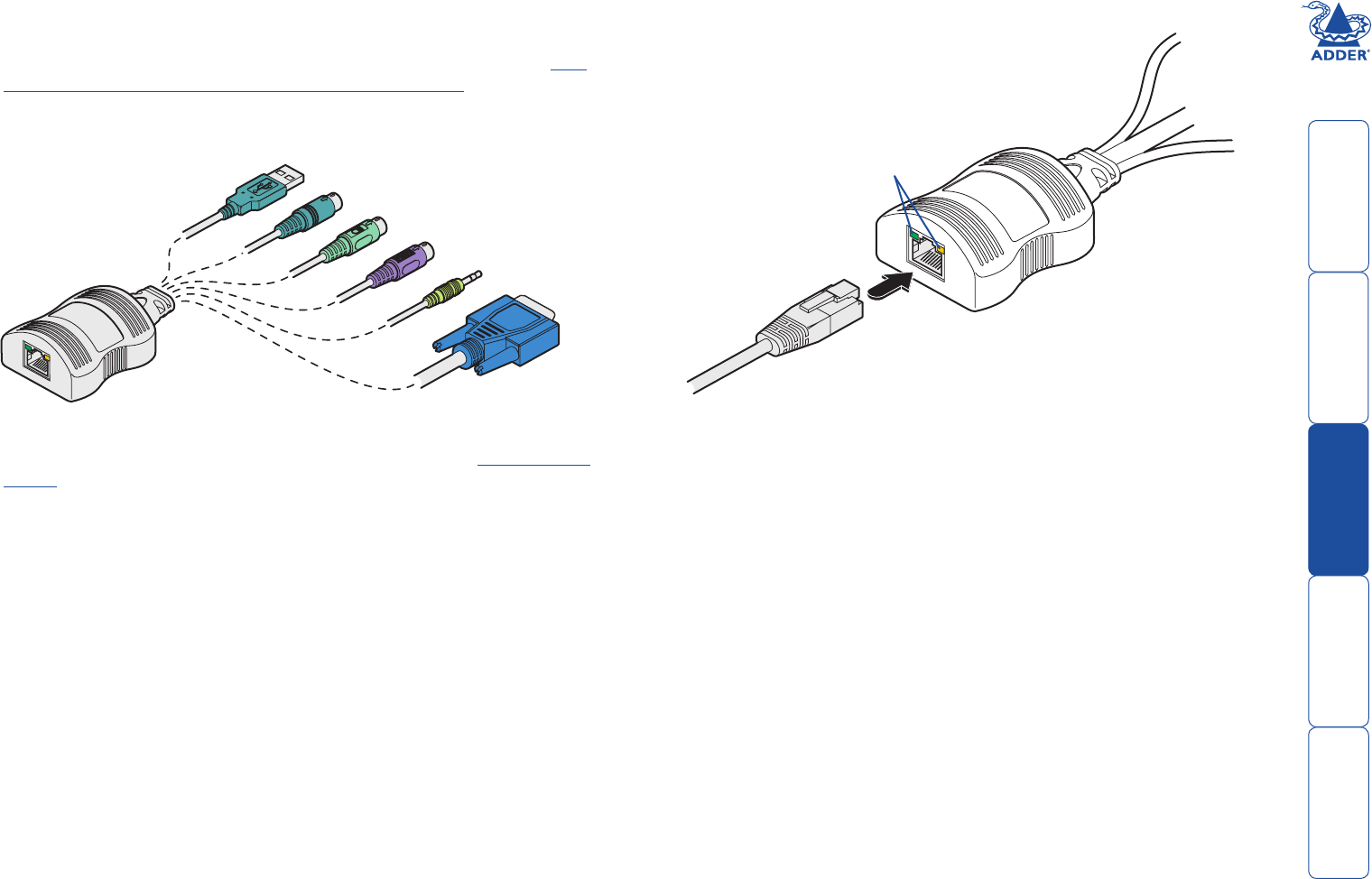
Connections at each CAM (local) unit
1 Where possible ensure that power is disconnected from the system(s) to be
connected. For CAMs with PS/2 keyboard and mouse connections, see Hot
plugging PS/2-style connections and mouse restoration.
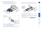
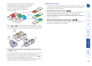
2 For each CAM, attach its various connectors to the relevant sockets on the
computer system.
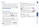
4 For each cable run, attach the cable connector to the
socket of the CAM. The other end of each cable run
will attach to the remote X200 module.
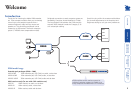
Computer
Access
Module
Category 5, 5e or 6 cable
to X200 module
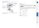
Green indicator - power present
Yellow indicator - signal activity
Note: CAMs derive power from the
computer system via the USB connector.
3 Lay a suitable length of category 5, 5e or 6 cabling between each computer
system/CAM and the location of the remote peripherals - see Cable length
advice.
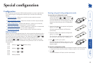
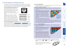
Video
PS/2-style mouse
PS/2-style keyboard
Audio
USB keyboard/mouse
Sun keyboard/mouse
A range of different
connector combinations
are made available
across the five CAM
formats