


61200051L1-1D ISU 2x64 Dual Port ISDN Service Unit User Manual 119
Appendix E
Connector Pinouts
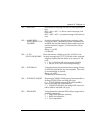
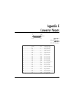
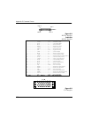
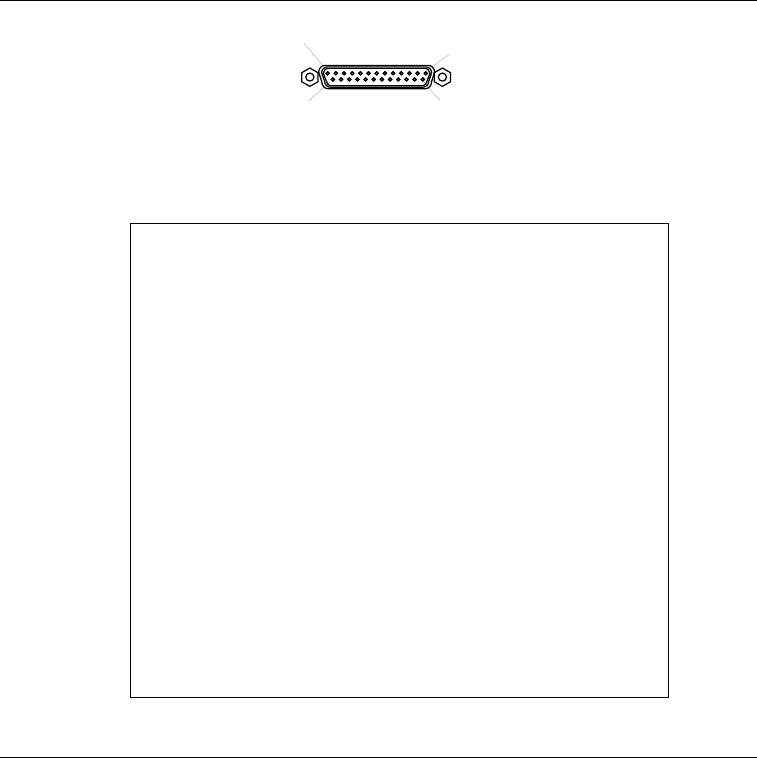
Figure E-1
EIA-232 Interface
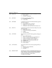
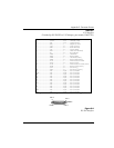
Table E-A
EIA-232 Interface
Pin Name I/O Description
1 ............................Shield ....................I/O........ Shield for cable
2 ............................TD.........................I............. Transmitted Data
3 ............................RD.........................O........... Received Data
4 ............................RTS........................I............. Request to Send
5 ............................CTS.......................O........... Clear To Send
6 ............................DSR.......................O........... Data Set Ready
7 ............................SG........................I/O........ Signal Ground
8 ............................CD........................O........... Carrier Detect
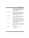
9 ............................NC .......................N/A ...... No Connection
10 ..........................NC .......................N/A ...... No Connection
11 ..........................NC .......................N/A ...... No Connection
12 ..........................NC .......................N/A ...... No Connection
13 ..........................NC .......................N/A ...... No Connection
14 ..........................NC .......................N/A ...... No Connection
..............................15 ........................TC ......... O Transmit Clock
16 ..........................NC .......................N/A ...... No Connection
17 ..........................RC ........................O........... Receive Clock
18 ..........................NC .......................N/A ...... No Connection
19 ..........................NC .......................N/A ...... No Connection
20 ..........................DTR .......................I............. Data Terminal Ready
21 ..........................NC .......................N/A ...... No Connection
22 ..........................RI ..........................O........... Ring Indicator
23 ..........................NC .......................N/A ...... No Connection
24 ..........................ETC.......................I............. External Transmit Clock
25 ..........................NC .......................N/A ...... No Connection
I = Input.............. O = Output........N/A = Not Applicable
PIN 13
PIN 1
PIN 25
PIN 14
FEMALE