


Unit Installation NetVanta 4300/4400 Series
48 Copyright © 2013 ADTRAN, Inc. 61200890E2-34R
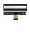
Wall Mounting NetVanta 4300/4400 Series
By following these instructions exactly, the NetVanta can be safely mounted to the wall.
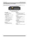
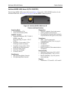
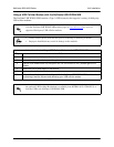
Instructions for Rack Mounting the NetVanta
Step Action
1 Position the NetVanta in a stationary equipment rack. This unit occupies 1U of space. To allow
proper grounding, scrape the paint from the rack around the mounting holes where the
NetVanta will be positioned.
2 Have an assistant hold the unit in position as you install two mounting bolts through the unit’s
brackets and into the equipment rack using a #2 Phillips-head screwdriver.
3 Proceed to the steps given in Supplying Power to the Unit on page 49.
• To avoid damaging the unit, use only the screws included in the shipment when
attaching mounting ears to the chassis.
• When wall mounting the NetVanta, care must be taken not to damage the power cord.
Do not attach the power cord to the building surface or run it through walls, ceilings,
floors, or openings in the building structure.
• The socket-outlet must be installed near the equipment and must be easily accessible.
• When wall mounting the NetVanta 4430, do not remove the SFP slot covers unless an
SFP has been installed in the slot.
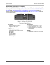
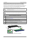
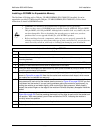
Instructions for Wall Mounting the NetVanta
Step Action
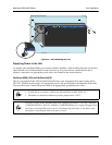
1
Remove the mounting ears from the NetVanta. Rotate them 90
o
so that the portion of the
bracket with the mounting holes is flush with the bottom of the chassis. Reattach them to the
chassis (see Figure 20 on page 49).
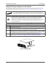
2 Decide on a location. All NetVanta 4000 Series units are mounted with the front panel facing
up. Keep in mind that the unit needs to be mounted at or below eye level so that the LEDs are
visible.
Important! Mount the chassis with LEDs facing up (not facing sideways or down).
Important! When wall mounting the NetVanta 4430, do not remove the SFP slot covers unless
an SFP has been installed in the slot.
3 Prepare the mounting surface by attaching a board (typically plywood, 3/4-inch to 1-inch thick)
to a wall stud using #6 to #10 (2.5-inch or greater in length) wood screws.
Important! Mounting to a stud ensures stability. Using sheetrock anchors may not provide
sufficient long-term stability.
4 Have an assistant hold the unit in position as you install two #6 to #10 wood screws through the
unit’s brackets and into the mounted board.
5 Proceed to the steps given in Supplying Power to the Unit on page 49.