


2
1
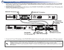
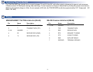
Rackmount the Units
Install the TRACER MPS system in a location that requires minimal antenna feedline length (the loss in this cable directly affects
overall system performance). The TRACER MPS should be mounted in a rack between the two BBP components of the TRACER systems
(see Figure 1 on page 2). Although no space is needed between the units, certain regulations may require at least 0.75” of space above
and below each BBP.
T
R
A
C
E
R
MAIN
STANDBY
OUT
NO COM NC MN COM SB
IN
ALARMS DC POWER RF
ANTENNA
TO DTE RS-232
MONITOR
T1B T1A
MAIN
TRACER
STANDBY
TRACER
MONITOR
POWER
MODULE
USE COPPER
CONDUCTORS ONLY
MAIN
OUT IN IN OUT B A B A
STAND
BY
MANAGEMENT
MANAGEMENT
IF ANTENNA
IF ANTENNA
T1AT1B
T1AT1B
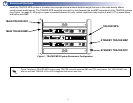
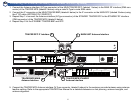
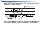
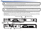
Figure 1. TRACER MPS System Rackmount Configuration
TRACER MPS
STANDBY TRACER BBP
MAIN TRACER RFC
MAIN TRACER BBP
STANDBY TRACER RFC
Figure 1 displays a TRACER MPS system using TRACER units with separate BBP and RFC components. The TRACER MPS can
also be used with TRACER 4103 or 4203 integrated rackmount radio units.