


3
2
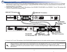
Creating the VT100 Chain
A single VT100 connection through the TRACER MPS provides access to both the primary (MAIN) and SECONDARY TRACER units.
Follow the steps below to create the VT100 chain.
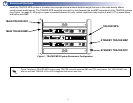
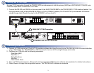
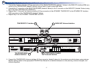
1. Connect the RS-232 port (DB-25) on the rear panel of the MAIN TRACER BBP to the TRACER MPS VT100 interface (labeled 1 on
the figure below) using the provided DB-25 (MALE) to RJ-45 (FEMALE) adapter (P/N 3196ADPT010) and standard 8-conductor
straight-though cable. Repeat the step for the STANDBY unit (see label 2).
T
R
A
C
E
R
MAIN
STANDBY
OUT
NO COM NC MN COM SB
IN
ALARMS DC POWER RF
ANTENNA
TO DTE RS-232
MONITOR
T1B T1A
MAIN
TRACER
STANDBY
TRACER
MONITOR
POWER
MODULE
USE COPPER
CONDUCTORS ONLY
OUT IN IN OUT B A B A
MAIN
STAND
BY
MANAGEMENT
T1AT1B
STANDBY UNIT VT100 Connection
MAIN UNIT VT100 Connection
1
2
3
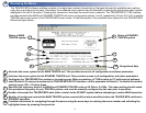
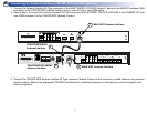
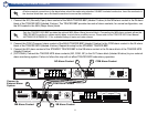
Connecting to the Unit
1. Connect a VT100 terminal (or PC with VT100 emulation software like HyperTerminal) to the TRACER MPS RS-232 console interface
using a DB-25 Male (for TRACER MPS) to DB-9 Female (for terminal or PC) straight-through serial cable.
2. Configure the COM port with the following parameters:
Data Rate: 9600
Data Bits: 8
Parity Bits: None
Stop Bits: 1
Flow Control: None
3. Open a VT100 terminal session. (Please refer to the appropriate VT100 terminal software documentation for detailed instructions.)
4. Press <Return> to begin the configuration session. The TRACER MPS Interface is now active.