


4
2
8
10
4
5
6
9
1
7
4
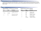
Reviewing the Menus
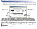
The TRACER MPS software interface consists of a single menu screen (shown below). Navigate through the available menu options
using the up and down arrow keys. Alternately, the numbered menu options may be selected by entering the appropriate menu number
displayed to the left of the option. Pressing the <space bar> activates the current menu selection. The TRACER MPS VT100 interface
provides access to the MAIN and STANDBY TRACER unit menus (using menu options 1 and 2, respectively). Press <Ctrl + R> to exit the
TRACER menus and return to the TRACER MPS menu screen. A brief description of the available menu options for the TRACER MPS
follows the figure below.
Navigational Help
Status of MAIN
TRACER system
Status of STANDBY
TRACER system
4
Activates the menu system for the MAIN TRACER unit. This provides access to all configuration and status parameters.
5
Activates the menu system for the STANDBY TRACER unit. This provides access to all configuration and status parameters.
6
Configures the TRACER MPS for modem or terminal access. When connecting a VT100 terminal or PC with terminal software,
select DISABLED.To connect a modem to the TRACER MPS RS-232 interface, set this parameter to ENABLED. To disable the modem
control, press <Ctrl + Z> three times.
8
Number of seconds the TRACER MPS waits (after a switch to the STANDY system) before attempting to restore MAIN operation.
9
Number of contiguous seconds the MAIN TRACER system must exhibit an alarm condition before the TRACER MPS switches to
STANDBY operation.
10
Provides instructions for navigating through the menus using the arrow keys or entering the menu number and activating the
highlighted menu by pressing the space bar.
7
Specifies the frequency band of the MAIN and STANDBY TRACER units as 5.8 GHz or 2.4 GHz. This menu setting should match
the operational frequency of your TRACER systems, and must be manually configured by the user prior to operation.