


5
MANAGEMENT
T
R
A
C
E
R
MAIN
STANDBY
OUT
NO COM NC MN COM SB
IN
ALARMS DC POWER RF
ANTENNA
TO DTE RS-232
MONITOR
T1B T1A
MAIN
TRACER
STANDBY
TRACER
MONITOR
POWER
MODULE
USE COPPER
CONDUCTORS ONLY
MAIN
OUT IN IN OUT B A B A
STAND
BY
T1B T1A
TRACER MPS
T1A/T1B Interfaces
TRACER MPS
MAIN T1A Interface
6
4
2
5
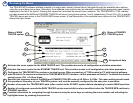
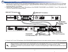
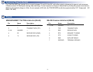
5 Connecting the T1 Interfaces
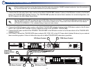
1. Connect the T1A interface (RJ-45) of the MAIN TRACER BBP (labeled 1 below) to the MAIN T1A interface (RJ-45) of the TRACER
MPS (labeled 2 below) using a straight-through T1 cable (ADTRAN P/N 3127004). Follow the same procedure to connect the T1B
interfaces (labeled 3 and 4 below).
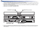
2. Repeat Step 1 to connect the T1A and T1B interfaces of the STANDBY TRACER BBP to the STANDBY T1A and T1B interfaces (RJ-
45) of the TRACER MPS (labeled 5 below).
MAIN UNIT T1B Interface
TRACER MPS
STANDBY T1A/B
Interfaces
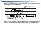
3. Connect the T1A and T1B interfaces of the TRACER MPS (labeled 6 above) to the public-switched network or CPE-type equipment.
When connecting the T1A/B interfaces of the TRACER MPS to the public switched network, use a T1 crossover cable (ADTRAN P/N
3125M011). For connections to other CPE-type equipment, such as an ADTRAN TSU, use a straight-through T1 cable
(ADTRAN P/N 3127004). For your convenience, 2 (each) T1 crossover and straight-through T1 cables are provided with the TRACER
MPS shipment.
TRACER MPS
MAIN T1B Interface
MAIN UNIT T1A Interface
1
3