


6
MANAGEMENT
T1B T1A
IF ANTENNA
T
R
A
C
E
R
MAIN
STANDBY
OUT
NO COM NC MN COM SB
IN
ALARMS DC POWER RF
ANTENNA
TO DTE RS-232
MONITOR
T1B T1A
MAIN
TRACER
STANDBY
TRACER
MONITOR
POWER
MODULE
USE COPPER
CONDUCTORS ONLY
OUT IN IN OUT B A B A
MAIN
STAND
BY
2
5
6
TRACER MPS Antenna Interface
TRACER MPS STANDBY
Antenna Interface
TRACER MPS MAIN
Antenna Interface
MAIN UNIT Antenna Interface
1
TRACER RFC IF Interface
3
4
TRACER BBP IF Interface
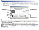
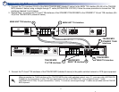
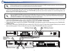
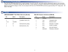
6a Connecting the Antenna Interfaces (TRACER BBP and RFC Systems)
1. Connect the Antenna interface (N-Type connector) of the MAIN TRACER RFC (labeled 1 below) to the MAIN RF interface (SMA con-
nector) of the TRACER MPS (labeled 2 below) using a male N-Type to male SMA cable.
2. Connect the IF connector on the MAIN TRACER BBP (labeled 4 below) to the IF connector on the MAIN RFC (labeled 3 below) using
the 6” RF cable (ADTRAN P/N 3125RF027).
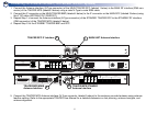
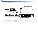
3. Repeat Step 1 to connect the Antenna interface (N-Type connector) of the STANDBY TRACER RFC to the STANDBY RF interface
(SMA connector) of the TRACER MPS (labeled 6 below).
4. Repeat Step 2 for the STANDBY TRACER BBP and RFC.
5. Connect the TRACER MPS Antenna interface (N-Type connector, labeled 5 above) to the customer provided antenna using antenna
feedline cabling. Refer to the appropriate TRACER User Manual for a detailed discussion on link planning, antenna loss/gain, and
antenna alignment.