


8 61221002L2-5B
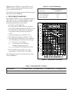
Figure 4. Deployment Guidelines
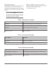
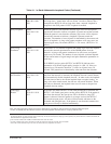
Table 9 lists the ADTRAN Litespan H2TU-C and
H2TU-R factors needed to calculate channel bank
power using Worksheet PW-1.
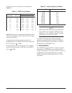
The Table 9 power factors are derived from the power
parameters listed in Table 10.
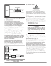
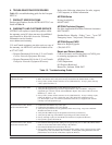
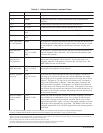
4. DEPLOYMENT GUIDELINES
The ADTRAN HDSL2 system is designed to provide
DS1-based services over loops designed to comply
with carrier service area (CSA) guidelines. CSA
deployment guidelines are given below.
1. All loops are nonloaded only.
2. For loops with 26-AWG cable, the maximum
loop length including bridged tap lengths is 9 kft.
3. For loops with 24-AWG cable, the maximum
loop length including bridged tap lengths is
12 kft.
4. Any single bridged tap is limited to 2 kft.
5. Total bridged tap length is limited to 2.5 kft.
6. The total length of multigauge cable containing
26-AWG cable must not exceed the following:
12 - {(3*L
26
)/(9 - L
BTAP
} (in kft.)
L
26
= total length of 26-AWG cable
excluding bridged taps (in kft.)
L
BTAP
= total length of all bridged taps (in kft.)
7. Recommended loop resistance for circuit
deployment is ≤ 750 Ω (9 kft. of 26 AWG).
This deployment criteria is summarized in the chart
shown in Figure 4.
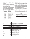
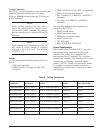
Power Bus
+5 V
-48 V Switch battery
Power consumption
Power dissipation
ADTRAN Litespan H2TU-C
and AH2TU-R
324 mA
125 mA
6 W
3 W
Table 10. Power Parameters
noitarugifnoCrotcaFnmuloCArotcaFnmuloCBrotcaFnmuloCCrotcaFnmuloCD
R-UT2HnapsetiLNARTDA423.0ANAN521.0
Table 9. Worksheet PW-1 Factors