161433105L2-5D Section 61433105L2, Issue 4
1. GENERAL
This practice provides installation and maintenance
procedures for the ADTRAN Series 5 Total Reach
®
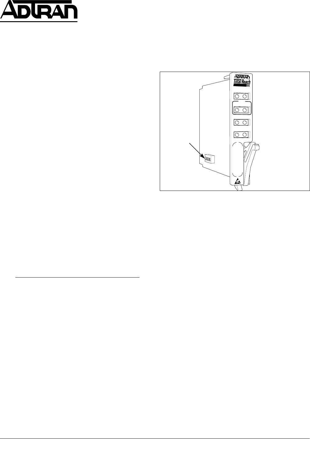
DDS-DP All-Rate DDS Dataport. Figure 1 is an
illustration of the ADTRAN Series 5 Total Reach
DDS-DP (P/N 1433105L5).
Revision History
This is the initial release of this document. Future
revisions will be described in this subsection.
Features
• 2-wire deployment
• Repeaterless operation
• Bridged tap tolerant
• Span power for remote Total Reach DDS-R
termination unit
• Utilization in SLC Series 5 and Series 2000 channel
banks
Series 5 Total Reach DDS-DP
Total Reach All-Rate DDS Dataport
Installation and Maintenance
Section 61433105L2-5D
Issue 4, June 2000
CLEI Code # 5SC531PF_ _
Trademarks: Any brand names and product names included in this document are trademarks,
registered trademarks, or trade names of their respective holders.
• Loop Quality Monitor and A/B signaling options
• Bidirectional DS0 loopback capability
• Transmits Mux Out of Sync code upstream during
out of service loop condition.
• Embedded Digital System 6 capabilities for remote
provisioning, and performance monitoring.
Description
The ADTRAN Series 5 Total Reach DDS-DP is a
functional replacement for the SLC
®
Series 5 OCU DP,
CLEI 5SCU48, delivering data at rates up to 64 kbps
using a single copper pair. Used in combination with the
Total Reach DDS-R termination unit, the Series 5 Total
Reach DDS-DP can accommodate extended loop
lengths, eliminating the need for DDS repeaters. The
Series 5 Total Reach DDS-DP span powers the Total
Reach DDS-R located at the customer premises. The
Total Reach DDS-R converts the 2-wire signal to the
traditional 4-wire Alternate Mark Inversion (AMI) signal
for presentation to the customer.
The ADTRAN Series 5 Total Reach DDS-DP
occupies a single channel position in the AT&T
®
SLC
Series 5 and Series 2000 or Series 5 compatible
channel bank. It provides the interface between a DS0
timeslot of the T-carrier data stream and the 2-wire
metallic loop extending to the customer premises. The
Figure 1. Series 5 Total Reach DDS-DP
CONTENTS
1. GENERAL ...................................................................... 1
2. INSTALLATION ........................................................... 3
3. TESTING ........................................................................ 3
4. REMOTE PROVISIONING AND DIAGNOSTICS ..... 5
5. DEPLOYMENT GUIDELINES .................................... 6
6. MAINTENANCE ........................................................... 7
7. WARRANTY AND CUSTOMER SERVICE ............... 8
Figures
Figure 1. Series 5 Total Reach DDS-DP ........................... 1
Figure 2. Total Reach DDS Circuit Diagram .................... 2
Figure 3. Option Switch ..................................................... 2
Figure 4. DS0 Bidirectional Loopback .............................. 4
Figure 5. DDS Trouble Codes ........................................... 5
Figure 6. Remote End Initiated Loopback, Local Loop .... 6
Figure 7. Remote End Initiated Loopback, Customer
Loop .................................................................... 6
Tables
Table 1. Option Settings..................................................... 2
Table 2. LED Indication..................................................... 4
Table 3. Latching Loopback Activation Sequence............ 5
Table 4. Alternating Loopback Activation Sequence........ 5
Table 5. Cable Type and Temperature Loss Data @
13.3 kHz ............................................................... 7
Table 6. Total Reach DDS Insertion Loss
Measurements ...................................................... 7
Table 7. Compliance codes ................................................ 7
1433105
SYN
C
SX
FE
CRC
NE
D
SU
Q
M
LBK
MAN
SW2
DDS-DP


