


361433105L2-5D Section 61433105L2, Issue 4
Quality Monitor
When QM (SW2-5) is ON, the TR DDS-DP monitors
the 2-wire loop and 4-wire customer interface for data
errors. Excessive errors on the 2-wire loop cause the
unit to send an alternating ASC (9Eh)/MOS (9Ah) to
the network. Excessive errors on the 4-wire customer
interface cause the unit to send an ASC to the
network. In both cases customer transmission is
blocked. When the trouble condition clears
transmission is automatically restored.
2. INSTALLATION
After unpacking the unit, inspect it for damage. If
damage is noted, file a claim with the carrier, then
contact ADTRAN. See Warranty and Customer
Service.
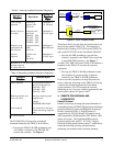
Tip/Ring Pair
The ADTRAN Series 5 Total Reach DDS-DP plugs
directly into a SLC Series 5 channel bank. No special
wiring is required. The 2-wire loop uses the T/R (Tip
and Ring) of the odd pair, pins 31 and 32 of the SLC
Series 5 backplane. The Total Reach DDS-R is not
polarity sensitive, therefore the Series 5 Total Reach
DDS-DP will operate even when the T/R pair is
reversed.
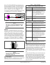
Span Power
Span powering is accomplished using -130 Vdc
measured from Tip to Ring. Voltage measured from
Tip to GND should indicate -130 Vdc or less
depending on input impedance of the measuring
device. However, voltage measured from Tip to Ring
should always indicate about -130 Vdc.
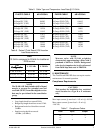
Synchronization and LED Indication
The Series 5 Total Reach DDS-DP and Total Reach
DDS-R typically require 30 to 90 seconds to
synchronize. When synchronized, the SYNC LOSS
indicator LED will turn off. If synchronization
cannot be achieved, check the T/R pair for open or
short circuit conditions or load coils. Refer to
Table 2 for synchronization and operational status
indication
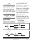
3. TESTING
Testing for the Series 5 Total Reach DDS-DP is
accomplished using the same test procedures for 4-wire
Zero Code
When Zero Code is enabled, the Series 5 Total Reach
DDS-DP allows DS0 bytes of all zeros to enter the
T-carrier data stream. On Alternate Mark Inversion
(AMI) facilities, this function should be disabled. B8ZS
carrier facilities that accommodate 64 kbps clear channel
operation do not require the zero code to be suppressed,
therefore zero code is automatically enabled when the 64
kbps rate has been selected.
Rate Selections
When 64K (SW2-1) is ON, the Series 5 Total Reach
DDS-DP operates at 64K Clear Channel.
When 19.2K (SW2-2) is ON, the Series 5 Total Reach
DDS-DP operates at 19.2 kbps.
When SW56 (SW2-3) is ON, the Series 5 Total Reach
DDS-DP enables Switched-56 operation.
NOTE
Only one rate should be selected. Service rates
of 64 kbps, 19.2 kbps, and Switched-56 are not
supported by the SLC Series 5 BCU. These
operating modes must be provisioned by
enabling switches on SW2. A manual rate
setting overrides BCU rate settings. The Series
5 Total Reach DDS-DP does not support 38.4
kbps.
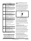
The Total Reach DDS-DP can also be used in the SLC-
2000 channel bank but the card must still be provisioned
similar to the SLC-5 options. That is, 64 kbps operation
the card is switch selected for 64 kbps while the assigned
slot is selected for 56 kbps. For 19.2 kbps operation the
card is switch selected for 19.2 kbps while the assigned
slot is set for 9.6 kbps.
Signaling
When A/B SIGNALING (SW2-4) is OFF, the unit
derives signaling from the incoming data stream. When
A/B SIGNALING is ON, the unit determines the state of
the A and B signaling bits using signals present on the
backplane of the channel bank. This method assumes
that proper signaling has been maintained throughout
network tandems and cross-connect systems.
NOTE
A/B signaling option is only applicable when
SW56 is selected; otherwise it is a “don’t care.”
C A U T I O N !
SUBJECT TO ELECTROSTATIC DAMAGE
OR DECREASE IN RELIABILITY.
HANDLING PRECAUTIONS REQUIRED.