


561433105L2-5D Section 61433105L2, Issue 4
ecneuqeS
noitcnuFnoitcnuF
noitcnuF
noitcnuFnoitcnuF
setyBdevieceR
kcabpoolevitcA
dnakcabpoolniatniaM
srorretibroftset
kcabpoolraelC
fosetybevitucesnocruoF
edockcabpooldeificeps
UCO-0101010X
USC-0001010X
USD-0011010X
htiwgnitanretlaetybataD
edockcabpool
:elpmaxe
0101010X/1DDDDDDX
setybatadevitucesnocruoF
kcabpoolgnitanretlatuohtiw
edoc
tiberact'noD=X
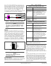
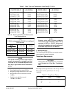
Table 4. Alternating Loopback Activation Sequence
ecneuqeS
noitcnuFnoitcnuF
noitcnuF
noitcnuFnoitcnuF
edoCetyB
forebmuN
devieceRdevieceR
devieceR
devieceRdevieceR
setyBsetyB
setyB
setyBsetyB
gnitsixeraelC
skcabpool
otecivedyfitnedI
depooleb
;pooloteraperP
edocPAMdnes
setyb03retfa
etavitcA
kcabpool
ninoitisnarT
)PIT(ssergorp
0101110X
tceleskcabpooL
)CSL(edoc
0SD-1010000X
UCO-1010101X
USC-1000110X
EIN-1000001X
delbanekcabpooL
)EBL(
0110101X
eciovdnE-raF
)VEF(
0101101X
fomuminiM
setybPIT53
fomuminiM
setybCSL53
fomuminiM
setybEBL001
fomuminiM
setybVEF23
dehsilbatseelbasidotderiuqersetybPIT53fomuminiM
.kcabpoolgnihctal
tiberaCt'noD=X
Table 3. Latching Loopback Activation Sequence
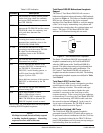
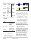
The TR DDS-DP will respond to a loopback
command initiated at the TROCU-R as follows:
• Pressing the TROCU-R LBK pushbutton once
will initiate a loopback at the TR DDS-DP
towards the customer. See Figure 6.
This allows data to be sent from the remote end to test
the local loop and the TROCU-R. This loopback is
indicated by a flashing CUST LED on the TROCU-R
and a solid CUST LED on the Total Reach DDS-DP.
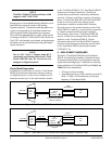
• Pressing the LBK pushbutton a second time
initiates a loopback at the TROCU-R towards the
4-wire DDS (CPE) interface. See Figure 7.
A solid CUST LBK LED on the TROCU-R indicates a
loopback at the TROCU-R towards the customer
equipment.
• Pressing the TROCU-R LBK pushbutton a third
time disables all current latching loopbacks
initiated by the TROCU-R LBK pushbutton.
If errors exist the loopbacks can help determine the
source; either the local loop or the TROCU-R. During
a remote end initiated loopback the Total Reach
system transmits ASC 9Eh towards the network,
indicating an out-of-service condition generated by the
remote end as shown in Figures 6 and 7.
4. REMOTE PROVISIONING AND
DIAGNOSTICS
Control Protocol
Remote access to provisioning and status information is
accomplished using ADTRAN Digital System 6 Message
protocol, defined in Control and Diagnostic Procedures
Practice, Section 6032991-6. Digital System 6 is
supported by the TPI 108/109 and 105 portable test set
and is supported by Hekimian React 2001 Release 1.900
remote test system. The Total Reach DDS network
elements comply with ANSI T1.107-1995, “ Digital
Hierarchy Format Specifications Annex G” which allows
remote provisioning, querying, and performance
monitoring via in-band control of network elements.
Figure 5. DDS Trouble Codes
Channel Bank
Open 2-wire Loop
DSU
TR
DDS-R
TR
DDS
DP
Customer Premises
ASC 9Eh
Channel Bank
ASC 9Eh
Open 4-Wire Customer
Interface
DSU
TR
DDS
DP
Customer Premises
TR
DDS-R
Alternating
MOS 9Ah/ASC 9Eh