


Table of Contents
Appendix D. Loop Status Messages 75
Appendix E. Connector Pinouts 77
List of Tables
Table B-A Express XR/XRT LEDs.................................................................... 63
Table E-A RS-232 Interface ................................................................................ 77
Table E-B Modem Interface .............................................................................. 78
Table E-C RJ-11 POTS Port Interfaces.............................................................. 79
Table E-D RJ-45 ISDN Line Interface ............................................................... 79
List of Figures
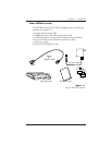
Figure 1-1 Express XR/XRT Contents ............................................................... 3
Figure 2-1 Dip Switches on Rear Panel.............................................................. 6
Figure 2-2 Standard ISDN Internet/Remote Access Application .................. 7
Figure 2-3 Installation Options ......................................................................... 10
Figure 2-4 ADTRAN Express Configuration Screen ..................................... 14
Figure 2-5 Unable to Auto-Detect ...................................................................... 15
Figure 2-6 Express Configuration Wizard Connection Tab .......................... 16
Figure 2-7 Express Configuration Wizard Tray Tool ..................................... 18
Figure 2-8 Preferences Tab ................................................................................. 19
Figure 2-9 Express XRT Disabled, External Analog Modem Enabled ........ 20
Figure 2-10 Express XR/XRT Enabled, External Analog Modem Disabled. 20
Figure 2-11 Unknown State ................................................................................. 20
Figure 2-12 Express Configuration Tray Tool Menu........................................ 21
Figure 2-13 VT 100 Terminal Configuration Menu .......................................... 24
Figure 2-14 VT 100 Terminal Status Buffer Menu ............................................ 25
Figure 3-1 External Analog Modem Application ........................................... 28
Figure 3-2 Express Configuration Wizard: Connect an External Modem . 32
Figure 3-3 No Modem Attached Error Message............................................. 32
Figure 3-4 HyperACCESS: Verifying External Modem Connection .......... 34
Figure 3-5 HyperACCESS: Enabling an External Analog Modem ............. 35
Figure 3-6 HyperACCESS: Disabling an External Analog Modem............ 36
Figure 3-7 Internal Analog Modem Application ............................................ 37
Figure B-1 Front Panel LEDs ............................................................................. 63
Figure E-1 RS-232 Interface ................................................................................ 77
Figure E-2 Modem Interface .............................................................................. 78
Figure E-3 Ground Pinouts ................................................................................ 79