


Chapter 2. Installation
6 Express XR/XRT Quick Start Guide 61200.153L1-13
SW 2: Off (Up) = Factory Default
On (Down) = Normal (previous settings saved)
If Switch 2 is set to the Off position, the unit continues to use the
factory default settings until Switch 2 is set to the On position.
Also, area code, phone numbers, SPIDS, and stored numbers are
cleared.
Express XRT Only:
SW 3: Off (Up) = Phone Volume Loud
On (Down) = Phone Volume Normal
SW 4: Reserved for future use.
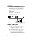
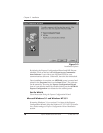
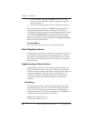
ISDN
OFF
ON
RS232POWER
1234
OFF
ON
1234
Figure 2-1
Dip Switches on Rear Panel
Connecting the Express XR/XRT
1. Turn the computer off.
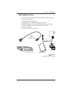
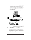
2. Using an RS-232 cable, (see the section Minimum Require-
ments) connect the end with the DB-25 connector to the port
labeled RS232 on the Express XR/XRT rear panel.
3. Connect the other end of the RS-232 cable to an available
serial COM port on the PC.
4. Plug the small round end of the AC power cord into the jack
labeled POWER on the Express XR/XRT rear panel.
5. Place the AC power cord plug into a 120 VAC electrical
outlet. The Express XR/XRT is now powered on.
6. Plug the RJ-45 connector (large end) of the RJ-45 to RJ-11
telephone cable into the jack labeled ISDN on the rear of the
Express XR/XRT.