


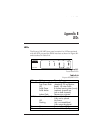


Appendix A. AT Commands and S-Registers
58 Express XR/XRT Quick Start Guide 61200.153L1-13
execute the command.
Range = 0 to 127
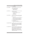
S14... MISC BITS ......... Miscellaneous bits (bit 8 is most significant bit).
Bit 2 = 1: Enables on screen echo of AT commands.
Bit 2 = 0:Disables on screen echo of AT
commands.
Bit 3 = 0:Enables AT responses from the
Express XR/XRT.
Bit 3 = 1:Disables AT responses from the
Express XR/XRT.
Bit 4 = 1:Enables AT responses to be displayed
in text form.
Bit 4 = 0:Enables AT responses to be displayed
in numeric form.
Bit 7 = 1:Disable PPP ACCM spoofing.
Bit 7 = 0:Enable PPP ACCM spoofing.
Bit 8 = 1:Ring indicator uses cadence.
Bit 8 = 0:Ring indicator remains on.
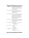
S15... ASYNC ................ Asynchronous BONDING method.
BONDING 0 = ADTRAN revision 0 (default)
1 = Multi-vender option
S22... MSG BITS .......... Miscellaneous message bits (bit 8 is most
significant bit).
Bit 5 = Bit 6 = Bit 7 = 1 Allows connect mes-
sage with baud rate.
Bit 5 = Bit 6 = Bit 7 = 0 Connect message
without baud rate.
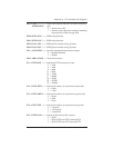
S25... DTR DETECT .... Determines time, in hundredths of a second, that
TIME must elapse before the Express XR/XRT recog-
nizes a change in DTR.
Range = 0 to 255
S27... PPP MODE ......... Value determines whether or not PPP will be a
single-link or multilink connection.
0 = Single-link operation (default)
1 = Multilink operation
2 = Use compression
S30... DTE CTS ............. Controls the operation of the DTE connector
CTS line.
0 = Follows RTS
1 = Force CTS
S31... DTE RTS ............. Controls operation of the RTS line.