


23
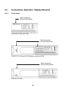
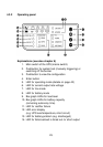
4.3.2 Operating panel
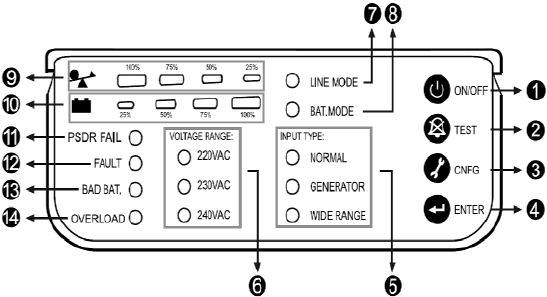
Explanations (see also chapter 6)
1. Main switch of the UPS (mains switch)
2. Pushbutton for system test (manually triggering) or
switching off the buzzer
3. Pushbutton to view the configuration
4. Enter button
5. LED for operating mode (details on page 42)
6. LED for current output rate voltage
7. LED for line mode
8. LED for battery mode
9. Bar graph LEDs for load level
10. Bar graph LEDs for battery capacity
(remaining autonomy time)
11. LED for rectifier failure
12. LED error display
(e.g. UPS overtemperature, short circuit)
13. LED for battery problem (e.g. discharged)
14. LED for fails/overload is timed out /or short output