124
In the option 002 replaceable parts list change cover plate from p/n 06023-00025 to p/n 06023-
00013. Add cover-plate p/n 06023-00010.
6015A In the parts list for the A1 Main Board Assembly change U1 to p/n 1906-0218. In the parts list
for the A5 Diode Board, change L1 to p/n 06011-80094.
CHANGE 10
6010A, 6011A,
6012B
In the parts list for the Mechanical Chassis change the following parts:
From: To:
Top cover 06032-00020 06032-00002
Bottom cover 06032-00019 06032-00003
Top trim 5041-8802 5040-7202
Side trim 5001-0539 5001-0439
Front frame 5021-8403 5021-5803
Feet 5041-8801 5040-7201
Strap handle 5062-3703 5060-8903
Handle ret. back 5041-8820 5041-6820
Handle ret. front 5041-8819 5041-6819
Lettered panel 06010-00009 06010-00008
6015A In the parts list for the A1 Main Board Assembly delete T3 and the following mechanical
attaching parts:
Screw, p/n 0515-0964
lock washer p/n 2190-0586
flat washer, p/n 3050-0893
clamp, p/n 06671-400002
bracket, p/n 06671-400003
CHANGE 11
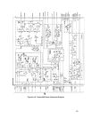
6010A In the Diode board A5 parts list and schematic diagram delete CR6.
6011A In the Diode board A5 parts list and schematic diagram change R17 from 2.87K 1%, p/n 0698-
3151 to 4.87K 1%, p/n 0698-4444.
6012B In the Diode board A5 parts list and schematic diagram change R2 from 2.87K 1%, p/n 0698-
3151 to 4.87K 1%, p/n 0698-4444.
CHANGE 12
6010A In the Diode board A5 parts list and schematic diagram change R2 from 2.87K 1% p/n 0698-
3151 to 4.87K 1%, p/n 0698-4444.
6011A In the option 002 (Appendix A) parts list and schematic diagram delete R57 and solder pin p/n
0360-1300.
6012B In the Diode board A5 parts list and schematic diagram change CR4 to p/n 1901-0887. Delete
heatsink (ref. Q2) p/n 06032-0018, heatsink bracket 06032-00017 and replace with inner heatsink
(ref. Q2) p/n 06032-00006 and outer heatsink (ref. Q2) p/n 06032-00018.


