98
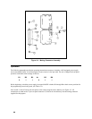
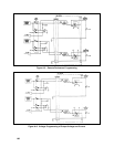
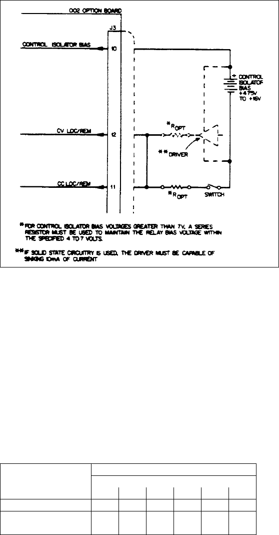
Figure A-3. Accessing Local Programming while in Remote Programming Mode
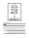
If solid state circuitry is used, connect the Control Isolator Bias to a driver capable of sinking 10mA of current, then
connect the driver's output to both of the LOC/REM terminals. Refer to Figure A-3. Either method will enable
relays K1 (CV) and K2 (CC) to switch regulation to the front panel VOLTAGE and CURRENT controls. For
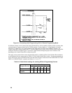
Control Isolator Bias voltages greater than 7V, a resistor (Ropt) must be used in series with the Control Isolator Bias
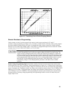
common or the Driver's output. Figure A-4 provides a graph for determining the proper series resistance value
depending on the Control Isolator Bias voltage being used.
The supply can be returned to the remote programming mode by switching off the Control Isolator Bias common or
by increasing the Driver's output signal to within 1V of the Control Isolator Bias voltage. If remote programming is
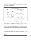
solely desired, leave the LOC/REM terminals open and make the proper connections to the RESISTOR/VOLTAGE
PROG. or CURRENT PROG. terminals (see Figures A-5, A-6, A-7).
Table A-2. Mode Switch settings for enabling different Programming Sources
Switch Pole Settings
Program Source
Mode
B1 B2 B3 B4 B5 B6
Resistance
001001
Voltage or
Current
010010


