


19
Frequency offset on/off
Sets the RF source to be swept at a fixed offset
frequency above the receiver as required in a swept
RF/IF, fixed LO, mixer test.
Service menu
Select the desired service test, service diagnostic,
service or verification mode.
Test Sequences
Description
Create, edit, save, or recall a series of front-panel key-
strokes to automate a measurement. Test sequences
may contain basic stimulus and measurement func-
tions (frequency, power, parameter, format, scale)
advanced operations (time domain, limit testing,
display marker values) and basic logical branching
(IF limit test fails DO sequence 5 or GOSUB).
Storage
Test sequences can be stored internally to a disk
drive and can be loaded from a computer over the
GPIB interface. Sequence 6 is saved in nonvolatile
storage and can be used as an autostart routine
when titled AUTO.
General purpose input/output
Read or write bits to the output port to control
external devices such as part handlers. Eight
output and five input TTL lines are available on
the parallel port.
Other functions
PAUSE/continue, wait, title sequence, print
sequence, duplicate sequence, pause, and select.
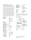
Time-domain (Option 010)
With the time-domain option, data from transmis-
sion or reflection measurements in the frequency
domain are converted to the time domain using
a Fourier transformation technique (chirp Z) and
presented on the display. The time-domain response
shows the measured parameter value versus time.
Markers may also be displayed in electrical length
(or physical length if the relative propagation veloc-
ity is entered).
Time stimulus modes
Two types of time excitation stimulus waveforms
can be simulated during the transformations,
a step and an impulse.
• Low-pass step
This stimulus, similar to a traditional time-
domain reflectometer (TDR) stimulus wave-
form, is used to measure low-pass devices. The
frequency-domain data should extend from
DC (extrapolated value) to a higher value.
• Low-pass impulse
This stimulus is also used to measure low-pass
devices.
• Bandpass impulse
The bandpass impulse stimulates a pulsed RF
signal (with an impulse envelope) and is used
to measure the time-domain response of band-
limited devices.
Windows
The windowing function can be used to modify
(filter) the frequency-domain data and thereby
reduce overshoot and ringing in the time-domain
response. Three types of windows are available:
minimum, normal, and maximum.
Gating
The gating function can be used to selectively
remove reflection or transmission time-domain
responses. In converting back to the frequency-
domain the effects of the responses outside the
gate are removed.
Remote Programming
Interface
GPIB interface operates to IEEE 488-1978 and IEC
625 standards and IEEE 728-1982 recommended
practices.
Addressing
The GPIB address can be verified or set from the
front panel via the local menu and can range from
0 to 30 decimal (factory set at 16).
Pass control
Allows the 8753ET/ES to request control of the
GPIB (when an active controller is present) when-
ever it needs to output to a plotter or printer.
System controller
Lets an 8753ET/ES become a controller on the
GPIB to directly control a plotter or a printer.
Talker/listener
Lets the 8753ET/ES become a GPIB talker/listener
when an external controller is present.
Transfer formats
Binary (internal 48-bit floating-point complex
format) ASCII 32- or 64-bit IEEE 754 floating-
point format.
User-accessible graphics
Using a subset of HP Graphics Language (HP-GL),
vector or text graphics may be written on the
8753ET/ES via GPIB. Up to 5 kbytes of data can
be stored at one time (4 bytes per vector, 2 bytes
per character).
Interface function codes
SH1, AH1, T6, TE0, L4, LE0, SR1, RL1, PP0, DC1,
DT0, C1, C2, C3, C10, E2