


10 Installation and Operation Guide
1 Introduction
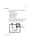
The column flow mixes with the makeup flow in the splitter. This mixture then
flows through lengths of uncoated, deactivated, fused-silica tubing to each
detector. These tubes act as flow restrictors. While the flow through each
restrictor changes with oven temperature, the ratio of the two flows at any
temperature is the same.
Details
The G3180B kit addresses several limitations of previous approaches to
splitting column effluent between two detectors:
Metal ferrules
The splitter uses metal column ferrules, which eliminate air leakage into the
sample stream. Unlike polyimide, metal ferrules do not loosen upon thermal
cycling of the oven. They also do not outgas contaminants or shed particles
(like graphite) that can result in chromatographic problems.
Microfluidic plate
The splitting hardware is based on microfluidic plate technology. This allows
very low dead volume connections between the column end and the two
detector restrictor tubes. The thin metal plate has fast thermal response and is
mounted solidly on the oven wall for ease of use. The interior plate surfaces
are deactivated to prevent adsorption by active compounds.
Constant pressure operation
The splitter uses a source of makeup gas supplied by electronic pneumatics
control (EPC). This maintains the splitter at a known and constant pressure.
Constant pressure allows easier splitting to vacuum detectors like the MSD. It
simplifies choice of splitter parameters, allowing all aspects of the
chromatographic setup to be calculated. Constant pressure makeup allows the
column to be run in constant flow mode while still maintaining a constant
split ratio between two detectors of different operating pressures such as the
FPD and the MSD. Because the EPC pressure can be time programmed, useful
operations like backflushing unwanted heavy materials from the column and
changing columns in MSD systems without venting are possible.