


Splitter Configurations 3
Installation and Operation Guide 27
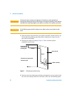
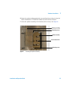
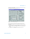
To use the tables, select the configuration you wish to set up. For example,
Configuration 1 splits column effluent equally between two atmospheric
pressure detectors (FID, TCD, ECD, FPD, and NPD). To plumb this system,
0.544-m lengths of 0.25-mm id uncoated deactivated fused silica tubing are
connected as restrictors from the splitter to the two detectors.
The makeup supply (either Aux EPC or PCM module) is set to 3.8 psig. This
will add sufficient makeup flow to the column flow to maintain the splitter
(and thus the column outlet) at 3.8 psi. Column flow can be varied from 0 to a
maximum flow which is determined by the upper temperature of the GC oven
program.
If Configuration 1 is used with a method that programs to 200 °C using helium,
the flow through each restrictor at 200 °C will be 7.3 mL/min. The total flow
will be 14.6 mL/min. The maximum column flow should be equal to the total
flow minus about 1 mL/min to ensure that there is some flow for the makeup
supply to regulate with.
The column flow at 200 °C should be no more than 13.6 mL/min. This becomes
important when the column is run in constant flow mode. If constant flow
mode is used with Configuration 1 and the method programmed to 400 °C, the
column flow should not exceed 6.8 mL/min ([3.9 + 3.9] –1).
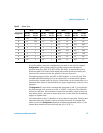
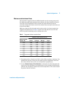
Table 3 Splitter flows
40 °C 200 °C 300 °C 400 °C
Configuration Flow R1,
mL/min
Flow R2,
mL/min
Flow R1,
mL/min
Flow R2,
mL/min
Flow R1,
mL/min
Flow R2,
mL/min
Flow R1,
mL/min
Flow R2,
mL/min
1 14.7 14.7 7.3 7.3 5.2 5.2 3.9 3.9
2 5.1 25.6 2.5 12.7 1.8 9.1 1.4 6.8
3 22110.70.70.540.54
4 44221.41.41.11.1
5 1 2 0.5 1 0.36 0.72 0.27 0.54
6 24120.711.40.531.06
7 0.4 2 0.2 1 0.14 0.7 0.1 0.5
8 0.8 4 0.4 2 0.28 1.4 0.21 1.1