


22 Installation and Operation Guide
2 Hardware Installation
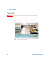
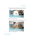
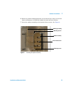
3 Open the plastic bag and remove the splitter assembly. Install a plastic cap
on the end of the makeup gas tubing. Place small pieces of tape over the
open end of the fittings.
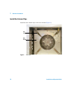
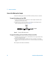
4 Prebend the tubing according to Figure 8. This will make splitter
installation much easier.
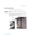
5 Push the end of the makeup gas tubing up through the top oven wall so that
the end of the tubing comes out in the hole of the valve box blanking plate.
CAUTION
Use extreme care to prevent any fragments of insulation or other material from
entering the makeup gas tubing or the fittings on the splitter assembly. Such materials
could block the internal passages in the splitter or the bore of the capillary restrictors.
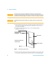
CAUTION
In the following steps, bend the tubing over an object such as your thumb to avoid
kinks.
Figure 8 Prebending the splitter tubing
45 mm
140 mm
60 mm
Dimensions are approximate
195 mm
Splitter assembly
Oven side wall
Up through hole
in oven top and
blanking plate
All bends are 90°