


26 Installation and Operation Guide
3 Splitter Configurations
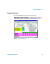
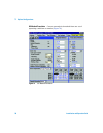
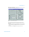
Typical Configurations
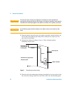
The important parameters when setting up a splitter are the lengths and
diameters of the restrictor tubes that go to the two detectors. The dimensions
of the restrictors are chosen to give the desired split ratio, flow to the detector,
and to minimize peak broadening.
The splitter restrictors are chosen based on:
• The range of column flows that will be used with the method
• The operating pressure of the two detectors
• The flow rate requirements of the two detectors
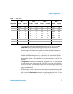
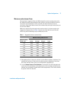
Table 2 lists typical splitting configurations. Table 3 shows the resulting gas
flows. All calculations assume helium as the carrier gas.
Table 2 Restrictor configurations
Configuration Det 1 Det 2 Split ratio,
Det 2/Det 1
Diam R1,
mm id
Length R1,
m
Diam R2,
mm id
Length R2,
m
1 atm* atm 1 0.25 0.544 0.25 0.544
2 atm atm 5 0.18 0.418 0.25 0.311
3 atm MSD,D** 1 0.18 1.060 0.18 2.890
4 atm MSD, T*** 1 0.18 0.530 0.18 1.440
5 atm MSD, D 2 0.18 2.130 0.18 2.890
6 atm MSD, T 2 0.18 1.064 0.18 1.443
7 atm MSD, D 5 0.10 0.507 0.18 2.890
8 atm MSD, T 5 0.18 2.660 0.18 1.443
* atm Atmospheric pressure detectors such as FID, TCD, ECD, FPD and NPD
** MSD, D MSD with diffusion pump or standard turbo pump (2 mL/min flow capability)
*** MSD, T MSD with performance turbo pump (4 mL/min flow capability); makeup pressure supply is set to 3.8 psig