


The Front Panel - At a Glance
10 Series N5700 User’s Guide
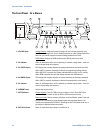
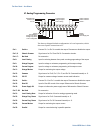
The Front Panel - At a Glance
VOLTAGE
PROT FINE
LIMIT/
OVP
UVL
OCP REM OUT ON
DC AMPS
CURRENT
DC VOLTS
POWER
1
14
17
18
19
2
15
16
3
13
10
4
11
5
12
9
6
7
8
CV CC
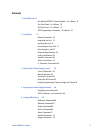
1 – VOLTAGE knob Voltage function
: Adjusts the output voltage, the over-voltage protection level,
and the under-voltage limit. If over-voltage protection or under-voltage limits have
been set, you cannot program the output voltage outside those limits.
GPIB address
: Selects the GPIB address when REM is pressed and held.
2 – CV indicator When lit, indicates that the unit is operating in constant voltage mode – with the
output voltage being held constant.
3 – DC VOLTS display LED display that normally displays the voltage measured at the sense terminals.
When LIMIT is pressed, the display indicates the programmed voltage setting.
When OVP/UVL is pressed, the display indicates either the OVP or UVL setting.
When REM is pressed and held, the display indicates the GPIB address.
4 – DC AMPS display LED display that normally displays the current measured at the output terminals.
When LIMIT is pressed, the display indicates the programmed current setting.
5 – CC indicator When lit, indicates that the unit is operating in constant current mode – with the
output current being held constant.
6 – CURRENT knob Adjusts the output current.
7 – OUT ON button Output function
: Press OUT ON to turn the output on or off. Press OUT ON to
reset and turn the output on after an OVP or OCP event has occurred.
Start-up function
: Selects between Safe-Start and Auto-Restart modes. Press and
hold the OUT ON button to toggle between Safe-Start and Auto-Restart. The
display cycles between SAF and AU7. Releasing the OUT ON button while one of
the modes is displayed selects that mode.
8 – OUT ON indicator When lit, indicates that the output is enabled or on.