


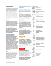
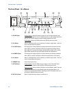
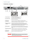

The Front Panel - At a Glance
Series N5700 User’s Guide 11
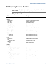
9 – REM button Mode function
: Press REM to put the unit into local mode. (This button can be
disabled with a Local Lockout command).
Address function: Selects the GPIB address. Press and hold the REM button for
three seconds to set the address with the Voltage knob.
10 – REM indicator When lit, indicates that the unit is in Remote mode.
11 – OCP button Enable function
: Press OCP to turn over-current protection on. Press OCP again to
turn over-current protection off.
Reset OCP
: When an over-current protection event occurs, press the OUT ON
button to enable the output and re-arm over-current protection.
12 – OCP indicator When lit, indicates that over-current protection is enabled or on.
13 – OVP/UVL button OVP function
: Press OVP/UVL once to set the over-voltage protection level with
the Voltage knob (the display shows OUP). You cannot set the over-voltage
protection lower than about 5% above the present output voltage setting.
UVL function
: Press OVP/UVL twice to set the under-voltage programming limit
with the Voltage knob (the display shows UUL).
You cannot set the under-voltage
protection higher than about 5% below the present output voltage setting.
14 – LIMIT button Limit function
: Press LIMIT to display the output voltage and current limit. For five
seconds the display shows the settings and then it returns to show the actual
output voltage and current.
Lock function
: Press and hold the LIMIT button to toggle between Locked front
panel and Unlocked front panel. The display will cycle between LFP and UFP.
Releasing the LIMIT button while one of the modes is displayed selects that
mode.
15 – LIMIT indicator When lit, indicates that the LIMIT button is pressed.
16 – FINE button Selects Fine or Coarse adjustment control. In Fine mode, the Voltage and Current
knobs operate with high resolution; in Coarse mode, with lower resolution
(approximately six turns).
17 – FINE indicator When lit, indicates that the unit is in Fine adjustment mode.
18 – PROT indicator When blinking, indicates that a fault has occurred.
OVP, OCP, OTP, Enable fail, and AC fail detection will cause the PROT indicator to
blink.
The PROT indicator may blink and the display indicate AC for a few seconds
after the unit is turned off because of residual
energy inside the unit.
19 – POWER switch Turns the power supply on or off.