


U2121A-101 Operating Guide 9
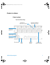
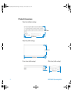
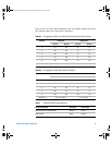
Each of the five RF switch channels uses two digital output pins and
two digital input pins during the operation.
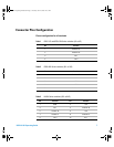
Table 6a IO mapping for 8762/3/4, 8765x-324 and N181x Series RF switches
Channel Control Bit Position Bit
State A State B State A State B
1O1O2I1I2
2O3O4I3I4
3O5O6I5I6
4O7O8I7I8
5 O9 O10 I9 I10
General IO O11, O12 & O13 I11, I12 & I13
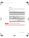
Table 6b IO mapping for 8765x-024 Series RF switches
Channel Control Bit Position Bit
State A State B State A State B
1O2O1I2I1
2O4O3I4I3
3O6O5I6I5
4O8O7I8I7
5O10O9I10I9
General IO O11, O12 & O13 I11, I12 & I13
Table 7 Position indicator stage definition
RF Switches Model Activated Deactivated
8732/3/4 Series and 875x Series OFF (0) ON (1)
N181x Series ON (1) OFF (0)
U2931A Operating Guide.book Page 9 Tuesday, June 10, 2008 10:17 AM