U2121A-101 Operating Guide 15
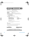
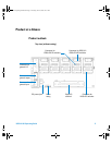
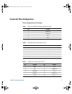
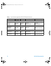
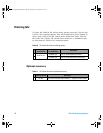
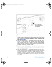
[1] SL1 to SL5 refers to the 8762/3/4 and 8765x-324 RF switch connectors for Ch1 to Ch5.
[2] X1 to X5 refers to the 8765x-024 RF switch connectors for Ch1 to Ch5.
[3] SV1 to SV5 refers to the N181x RF switch connectors for Ch1 to Ch5.
[4] X7 refers to the connector for general I/O on the switch driver board.
[5] X8 refers to the connector for general output on the switch driver board.
[6] X9 refers to the connector for general input on the switch driver board.
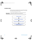
D. Launch the Agilent U2121A-Based RF Switch Driver
Software
1 Before attempting to start- up your U2121A- Based RF Switch Driver
Software, it is recommended to follow the step-by- steps
instructions below.
2 Plug in your instrument via the supported USB socket.
3 Go to Start > All Programs > Agilent IO Libraries Suite > Agilent Connection
Expert to launch the Connection Expert.
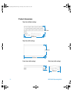
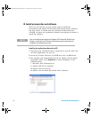
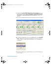
4 The detected U2121A will be visible on the Instrument I/O on this PC
explorer pane. Right- click on the U2121A instrument on the
explorer pane.
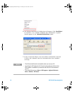
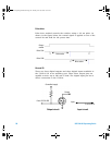
5 A context menu will appear as shown below. Select Send Commands
To This Instrument.
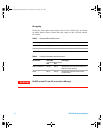
The total allowable current is 1500 mA. Please ensure that the total current
consumption is not more than 1500 mA.
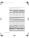
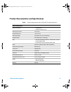
Before you proceed, ensure that your system meets the minimum system
requirements.
U2931A Operating Guide.book Page 15 Tuesday, June 10, 2008 10:17 AM