


32 U2121A-101 Operating Guide
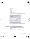
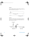
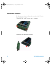
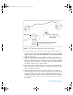
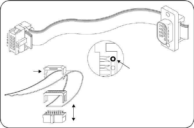
Figure B-2 Y1157A connector orientation and ribbon cable routing
3 Move the connectors to the ends of the cable, allowing for some
overlap on the D-Sub connector end and strain relief on the ribbon
cable connector end. Note the orientation of the connectors and
cable in Figure B- 2.
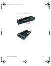
4 Align the metal contacts of the ribbon connector over cable pin 1
(Figure B-2) and the other pins, press the ribbon cable connector
onto the cable using a vise or clamp to press the contacts evenly
through the cable insulation. Continue to press the connector until
the metal contacts are no longer visible.
5 Fasten the strain relief clamp over the cable and into the ribbon
cable connector as shown in Figure B- 2. Remove any excess cable
after the clamp is in place.
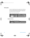
6 Align the metal contacts of the D- Sub connector over cable pin 1
and the other pins, press the D- Sub connector onto the cable using
a vise or clamp to press the contacts evenly through the cable
insulation. Continue to press the connector until the metal contacts
are no longer visible. Remove any excess cable after the connector
is in place.
Strain relief
Pin 1 of ribbon cable
Align connector contacts
over cable lines
“Press” until metal contacts are no longer
visible (same for D-Sub connector)
U2931A Operating Guide.book Page 32 Tuesday, June 10, 2008 10:17 AM