


14 U2121A-101 Operating Guide
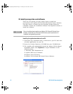
3 Disconnect any instrument that is connected to your PC and close
all other applications on your PC.
4 Double- click the saved installation file to begin installation.
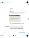
5 If you do not have any of the prerequisites installed, the
InstallShield
Wizard
software prerequisite will appear.
6 Click OK to begin the installation of the listed missing
prerequisites.
7 Once the above installation has completed, installation of the
Agilent U21210A-BAsed RF Switch Driver Software will proceed as
normal.
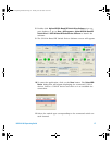
8 Follow the instructions on your screen to begin the installation.
9 Click Finish once the installation has completed.
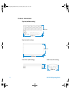
C. Connect the hardware solution to your PC
1 Connect the U2121A- 101 board digital IO terminal to the U2121A
terminal block using the interface cable.
2 Connect the power adapter to the RF switch driver board’s DC
power jack.
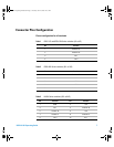
3 Connect the RF switches as below:
i For 8762/3/4 and 8765x-324 RF switches, connect to any SL1
[1]
to SL5
[1]
slot.
ii For 8765x-024 RF switches, connect to any X1
[2]
to X5
[2]
slot.
iii For N181x RF switches, connect to any SV1
[3]
to SV5
[3]
slot.
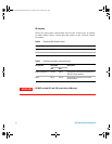
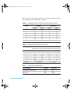
4 Connect other types of load to general IO, X7
[4]
or X8
[5]
and X9
[6]
if required. The load voltage is 24 VDC. The maximum load should
not exceed 300 mA per output channel and 3 mA per input
channel.
NOTE
Connect only one type of the RF switch to one channel. Do not use multiple
switches simultaneously on one channel.
U2931A Operating Guide.book Page 14 Tuesday, June 10, 2008 10:17 AM