28
Header
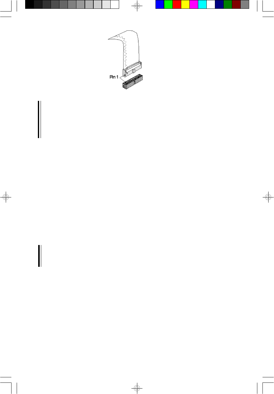
Note:
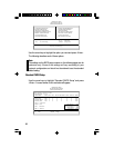
An IDE cable with a standard 40-pin connector (without the keying
mechanism) can be installed in the shrouded PCI IDE header. Be ex-
tremely careful to match the colored edge of the ribbon with pin 1 of the
header.
Connecting the Hard Disk Cable
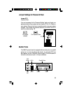
1. If you are connecting two hard drives, install the 40-pin connector of
the IDE cable into the primary shrouded IDE header (connector
J11). If you are adding a third or fourth IDE device, install the 40-
pin connector of the other IDE cable into the secondary shrouded
IDE header (connector J12).
2. Install the other 40-pin header connector(s) into the device with the
colored edge of the ribbon cable aligned with pin 1 of the drive
edge connector(s).
Note:
Refer to your disk drive user’s manual for information about selecting
proper drive switch settings.
Adding a Second IDE Hard Drive
When using two IDE drives, one must be set as the master and the
other as the slave. Follow the instructions provided by the drive manu-
facturer for setting the jumpers and/or switches on the drives.


