46
On-Chip Primary PCI IDE and On-Chip Secondary PCI IDE
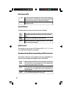
These categories allow you to enable or disable the primary and sec-
ondary IDE controller. The default is Enabled. Select Disabled if you
want to add a different hard drive controller.
Integrated Peripherals
IDE HDD Block Mode
Enabled
Disabled
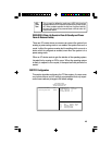
The IDE HDD uses the block mode. The system BIOS will
check the hard disk drive for the maximum block size the
system can transfer. The block size will depend on the type
of hard disk drive installed.
The IDE HDD uses the standard mode.
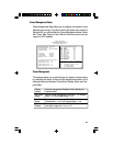
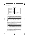
ROM PCI/ISA BIOS
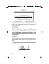
INTEGRATED PERIPHERALS
AWARD SOFTWARE, INC.
IDE HDD Block Mode
IDE Primary Master PIO
IDE Primary Slave PIO
IDE Secondary Master PIO
IDE Secondary Slave PIO
On-Chip Primary PCI IDE
On-Chip Secondary PCI IDE
PCI Slot IDE 2nd Channel
Onboard FDD Controller
Onboard Serial Port 1
Onboard Serial Port 2
UART 2 Mode
Onboard Parallel Port
Onboard Parallel Mode
: Enabled
: Auto
: Auto
: Auto
: Auto
: Enabled
: Enabled
: Disabled
: Enabled
: COM1/3F8
: COM2/2F8
: Standard
: 378/IRQ7
: SPP
ESC
F1
F5
F6
F7
:Quit
:Help
:Old Values
:Load BIOS Defaults
:Load Setup Defaults
↑↓→←
PU/PD/+/-
(Shift) F2
:Select Item
:Modify
:Color
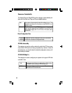
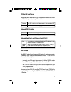
Auto
0-4
The BIOS will automatically set the system according to your
hard disk drive’s timing.
You can select a mode that matches your hard disk drive’s
timing. Caution: Do not use the wrong setting or you will
have drive or CD-ROM errors.
IDE Primary Master/Slave PIO and IDE Secondary Master/Slave
PIO
Your system supports five modes, 0 (default) to 4, which primarily differ
in timing. When Auto is selected, the BIOS will select the best available
mode after checking your hard drive or CD-ROM.
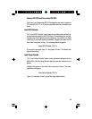
USB Controller : Disabled


