


10 AT-8700XL Series Switch
C613-04042-01 REV D
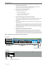
System LEDs
System LEDs on its front panel indicate the switch’s operational status.
1. DC models of the switches do not have an RPS connector and the RPS LED will not function.
The AT-8700XL Series Hardware Reference has further troubleshooting
information, including information on Switch Port and Uplink Module LEDs.
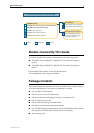
Documentation and Tools CD-ROM
The Documentation and Tools CD-ROM bundled with each AT-8700XL Series
switch contains the complete Documentation Set for your switch and its
expansion options, as well as tools for managing the switch. This includes:
■ The AT-8700XL Series Safety and Statutory Information booklet, which
provides safety and statutory information for the AT-8700XL Series switch
and its expansion options.
■ The AT-8700XL Series Hardware Reference, which provides detailed
information on the hardware features of AT-8700XL Series switches.
■ This Quick Install guide.
■ The AT-8700XL Series Software Reference, which provides detailed
information on configuring the switch and its software.
■ The Uplink Module Quick Install Guide, which outlines the procedure for
installing an Uplink Module; and the Uplink Module Hardware Reference,
which provides detailed information on Uplink Modules.
■ AT-TFTP Server for Windows for downloading software releases.
■ Adobe Acrobat Reader for viewing online documentation.
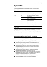
System LEDs
LED State Function
Power Green The switch is receiving power and the voltage
is within the acceptable range
Fault Red The switch or management software is
malfunctioning
1 flash A switch fan has failed. (The LEDs will not
indicate an RPS fan failure.)
3 flashes If an RPS is connected, the switch’s PSU (Power
Supply Unit) has failed
4 flashes If RPS monitoring is enabled, the RPS PSU has
failed
5 flashes If RPS monitoring is enabled, an RPS is not
connected or is not operational
RPS
1
(Redundant
Power Supply)
Green An RPS is connected to the switch